This thread has been locked.

If you have a related question, please click the "Ask a related question" button in the top right corner. The newly created question will be automatically linked to this question.

ADS42LB69EVM: Pre Programming requirements for ADS42LB69EVM

Part Number: ADS42LB69EVM

Hi,

We had manufactured and Assembled ADS42LB69EVM using the Gerber files available from TI website. We have made a set up with the capture card TSW1400EVM (TI's EVM) . But through USB interface we are not able to detect ADC on the GUI.

Please confirm whether any programming of the FTDI chip FT245RL is needed before making the connection or does the device come pre-programmed?
If we need to program the device, please share the software files and procedure.

Regards,
Vijetha

  • Hi,

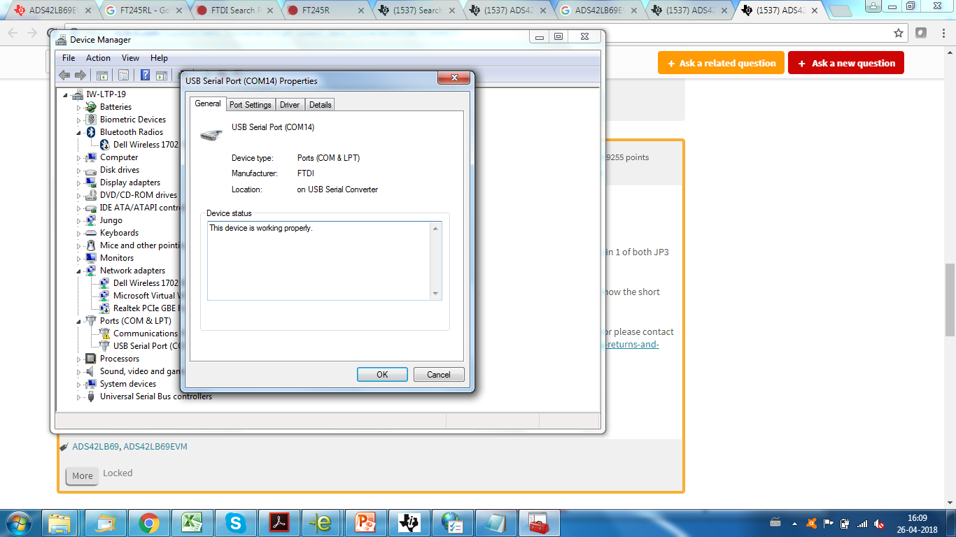
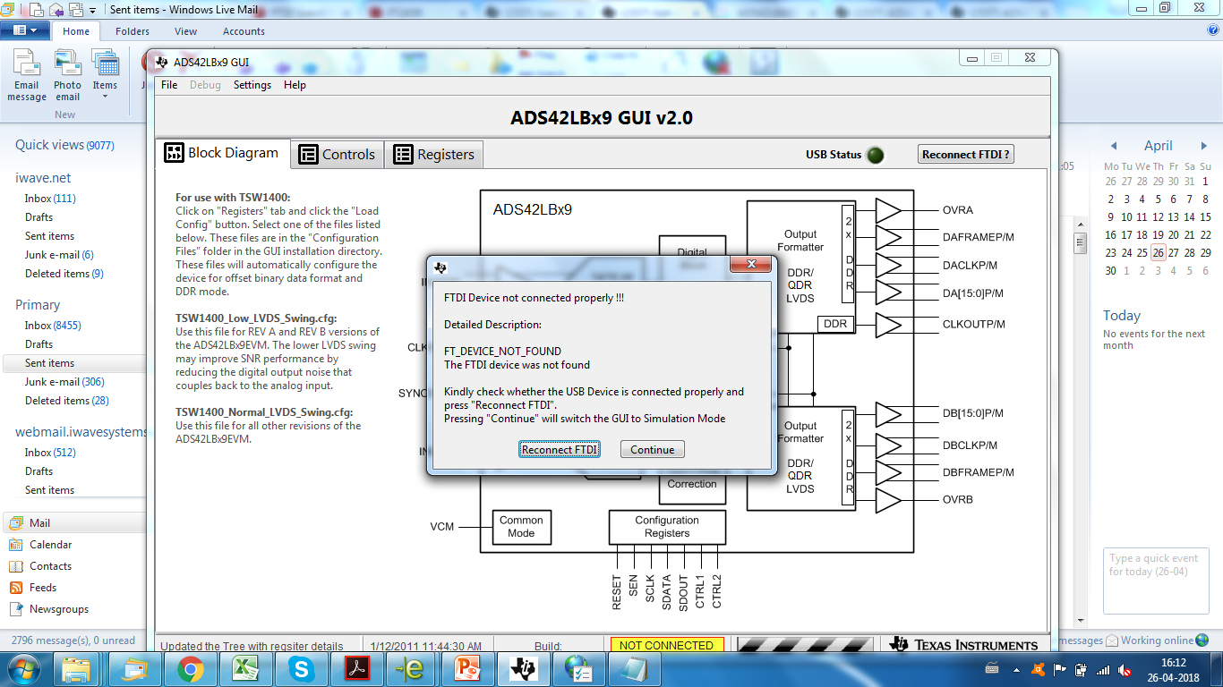
    We also tried the same set up with ADS42LB69EVM provided by TI. And it is working working absolutely with that. But when we replace TI's EVM with ADS42LB69EVM manufactured and assembled by iWave (using Gerber files from TI website) the connection is not getting established. However we are able to see FTDI USB connection on Device manager (see image 1) Also see Image 2 for screenshot of device connection status.

    Regards,

    Vijetha

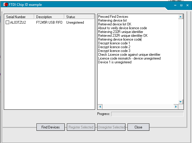
  • We are able to detect and read the Chip ID of the USB to Serial Interface Bridge IC correctly in the board - indicates FTDI chip is not malfunctioning.
    This confirms the USB interface to be working as expected, but the Serial Interface connected to the ADC looks buggy.

  • Hi Vijetha

    I'm not that familiar with the setup of the FT245RL on that EVM.

    Let me check with a colleague and respond in more detail tomorrow.

    Best regards,

    Jim B

  • Hi,

    Waiting for your guidelines.

    Regards,

    Vijetha

  • Further Debug,

    We understood from datasheet that the communication interface between ADC - FTDI is a simple custom serial communication, but for the FTDI chip to adhere to this protocol we need to configure the FTDI IC (it's internal EEPROM) to same.
    We have tapped the serial interface between ADC and FTDI chip. There is no communication happening in these lines when we try to connect using ADC GUI (ADS42LBx9 GUI). So please share the .rom file that can be programmed to FTDI EEPROM for successful communication to ADC IC.

    Regards,
    Vijetha
  • Hi Vijetha

    You are correct, the internal EEPROM in the FT245R device does need to be programmed so the board can be recognized.

    The required software tool to accomplish the programming is FT PROG. It can be downloaded here: http://www.ftdichip.com/Support/Utilities.htm#FT_PROG

    The version I downloaded today is 3.6.88.402.

    You need to use that tool and scan (magnifying glass icon) to find the connected un-programmed board, and then program it with the needed information. This can be done using the template file attached here. I created this template from the FTDI Chip on a working ADS42LB69EVM that I have.

    /cfs-file/__key/communityserver-discussions-components-files/73/6253.ADS42B69EVM-Template-for-FT245R.xml

    Once you have the board scanned, locate the template file from FT Prog and then use the Apply Template command. After applying the template you will need to click the Program icon (lightning bolt icon) to write the EEPROM information.

    For more details the FT_PROG User Guide will be helpful: http://www.ftdichip.com/Support/Documents/AppNotes/AN_124_User_Guide_For_FT_PROG.pdf

    I hope this is helpful.

    Best regards,

    Jim B

  • Hi,

    We tried this, programming was successful but still ADC did not connect on GGUI, same issue persist. And we scoped SPI pins; we do not see any proper signal toggling.

    Here we attached the FTDI EEPROM file read back after programming. Please compare once against your working EVM's FTDT EEPROM content.

    Can we have a webEx call, please let me know (vijethahn@iwavesystems.com) on your availability and call details.

    Device: 0 [Loc ID:0x14] 
    
    Word  MSB
    0000: 4001 0403 6001 0600 2DA0 0008 0000 0A98   @...`...-.......
    0008: 20A2 12C2 0000 0000 030A 0046 0054 0044    ..........F.T.D
    0010: 0049 0320 0046 0054 0032 0034 0035 0052   .I. .F.T.2.4.5.R
    0018: 0020 0055 0053 0042 0020 0046 0049 0046   . .U.S.B. .F.I.F
    0020: 004F 0312 0041 004C 0032 0055 004C 0049   .O...A.L.2.U.L.I
    0028: 0047 0046 0000 0000 0000 0000 0000 0000   .G.F............
    0030: 0000 0000 0000 0000 0000 0000 0000 0000   ................
    0038: 0000 0000 0000 0000 0000 0000 0000 EDA1   ................

  • Hi,

    The issue is solved. I will share the details later. Thank you for the great support.

    Regards,

    Vijetha

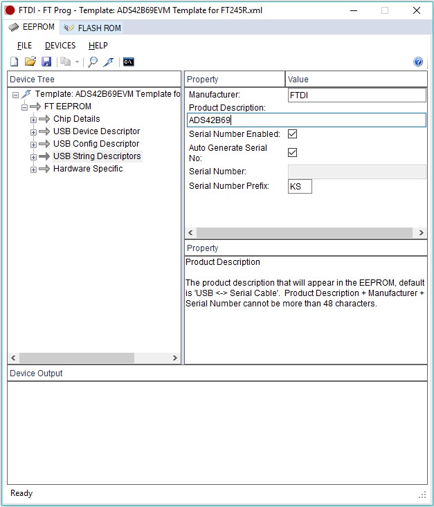
  •  We had to update Product description in USB String Descriptor as ADS42B69. By default something else was written there. After doing this change we programmed again and ADC got detected on GUI!

  • That's good news, thanks for the update!
    Regards,
    Jim B