This thread has been locked.

If you have a related question, please click the "Ask a related question" button in the top right corner. The newly created question will be automatically linked to this question.

ADS1018: SPI issue

Part Number: ADS1018
Other Parts Discussed in Thread: ADS1118EVM, , ADS1118, TXB0104

Hello team,

Posting for a colleague:

I am developing a LabVIEW program to communicate with the ADS1018 using a NI USB-8451 SPI interface. I am using one of TI’s ADS1118EVM demo boards we purchased from TI.  


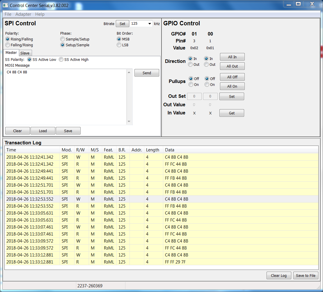
I am scoping the –CS, SCLK, DIN & DOUT/-DRDY signals and from what I can tell I am sending the part legitimate commands. I have attached a photo of the scope showing the data stream. Top yellow trace is CS. Green is the SCLK. Blue trace is data being sent to the ADS1018. Purple is what the ADS1018 is sending back. 


Referring to the ADS1018 Datasheet (SBAS526C Nov. 2012-Revised Nov.2015) page 18, Fig. 13, 32-Bit Data Transmission Cycle With Config Register Readback, as I understand it, when I send a 32 bit transmission it should respond with  “Data MSB – Data LSB – CONFIG MSB- CONFIG LSB”.  As you will see both on the scope and in my read back data it is not giving me this response. The response I get makes no sense. It is however, always the same regardless of whether I set it up for “Continuous-conversion mode” OR “Power-down and single-shot modes”.


  1. Am I sending the MSB and LSB in the correct order?  I am currently sending it CONFIG MSB- CONFIG LSB – CONFIG MSB- CONFIG LSB. Per Fig. 13.
  2. I have adjusted the SCKL frequency to several values from 100kHz up to 1MHz and this has had no effect. (Note: the waveform example I have attached is 100KHz SCLK frequency.)
  3. I have tried both Continuous-conversion mode and Power-down and single-shot modes.
    1. I am operating under the assumption that in Continuous-conversion mode, I have to send at least 1 Config command to the device to start it. With subsequent commands, I am expecting to see data.   
    2. I have the  NI USB-8451 configured to ClockPolarity is set to Idle Low, clock on second edge, 8-Bits/sample. This is per Fig. 1 on page 8 of the Data Sheet.

I know that the NI USB-8451 is working properly because this same system communicates with a Linear Technologies Battery monitor device just fine. It sits on the same SPI buss using a different CS line.

Anything we can look into to help isolate what's going wrong?

Thanks!

Nate

  • Thanks, Nate. I will monitor this to see if there is any response. I am still spinning my wheels on the problem.
  • Hi John,

    Just so we are clear, are you using the ADS1118EVM or ADS1118 Booster Pack?

    One thing I find odd in the scope shots is the DOUT appears to be 5V where the CS, SCLK and DIN appear to be 3.3V.  How are you powering the EVM? And how do you have the EVM physically connected to the NI box? Do you have any pictures of your setup?

    Best regards,

    Bob B

  • Bob,

    I have the ADS1118EVM.

    Good point about the power. The ADS1118EVM is being powered by 5V coming from the NI USB-8451. DOUT has a 5K pull up to that 5V source also which is why it has a 5V swing. On the other hand, the NI USB-8451 is programmed to provide 3.3 signals.

    I did this because the Electronics Design Engineer that developed the final system my software is going to talk to has the ADS1118's powered with 5V. I just checked the spec. and note that VIH is .7 VDD or .35 volts. So what I am interpreting is that the ADS1118 is probably not seeing the incoming data stream. What is your thoughts on this?

    If you think this is causing the problem this will be a problem for us as the NI USB-8451 highest output voltage on the outgoing data is 3.3 volts. I will likely have to have the designer revise the board.

    Thanks,

    John
  • I rounded up a 3.3 V supply to power the ADS1118EVM and it is now communicating. I have alerted the Electronics Design Engineer that he needs to put a 3.3 V regulator in his circuit design to power the ADS1118's

    Thanks for your help Bob.
  • Hi John,

    Yes, the voltages need to match for proper communication. To verify that you can communicate you could drop the supply voltage on the ADS1118EVM to 3.3V (which you have already tried). If the end design requires the ADS1018 to operate at 5V, but the micro (or spi master source) is running at a lower voltage, then you would need to add a level shifter between devices. One example would be the TXB0104.

    Best regards,
    Bob B

  • All,

    I did run a set of tests with the ADS1118EVM. I used a Total Phase Aardvark as the SPI emulator which is about 3.3V for the digital communication. If I run the supply up from 3.3V to about 5.2V, I start to get some bad communication right at 5.0V or so (sometimes it works, sometimes it doesn't).

    Here's the datalog:

    In this run, I start at 3.3V supply. go to 4V, and then increment in 0.2V steps. I have a bit of a rat's nest of wires, so the SPI didn't look clean on the scope, but I think the mismatch in digital supplies is the problem. Just in case there's something else, is there a way for you to drop the ADC supply to verify that this is the issue?

    Joseph Wu