This thread has been locked.

If you have a related question, please click the "Ask a related question" button in the top right corner. The newly created question will be automatically linked to this question.

ADS114S08: Unable to get the desired ADC output

Part Number: ADS114S08

Hi all

I am getting strange but symmetric ADC result from ADS114S08 eval board (attached picture of the result graph)

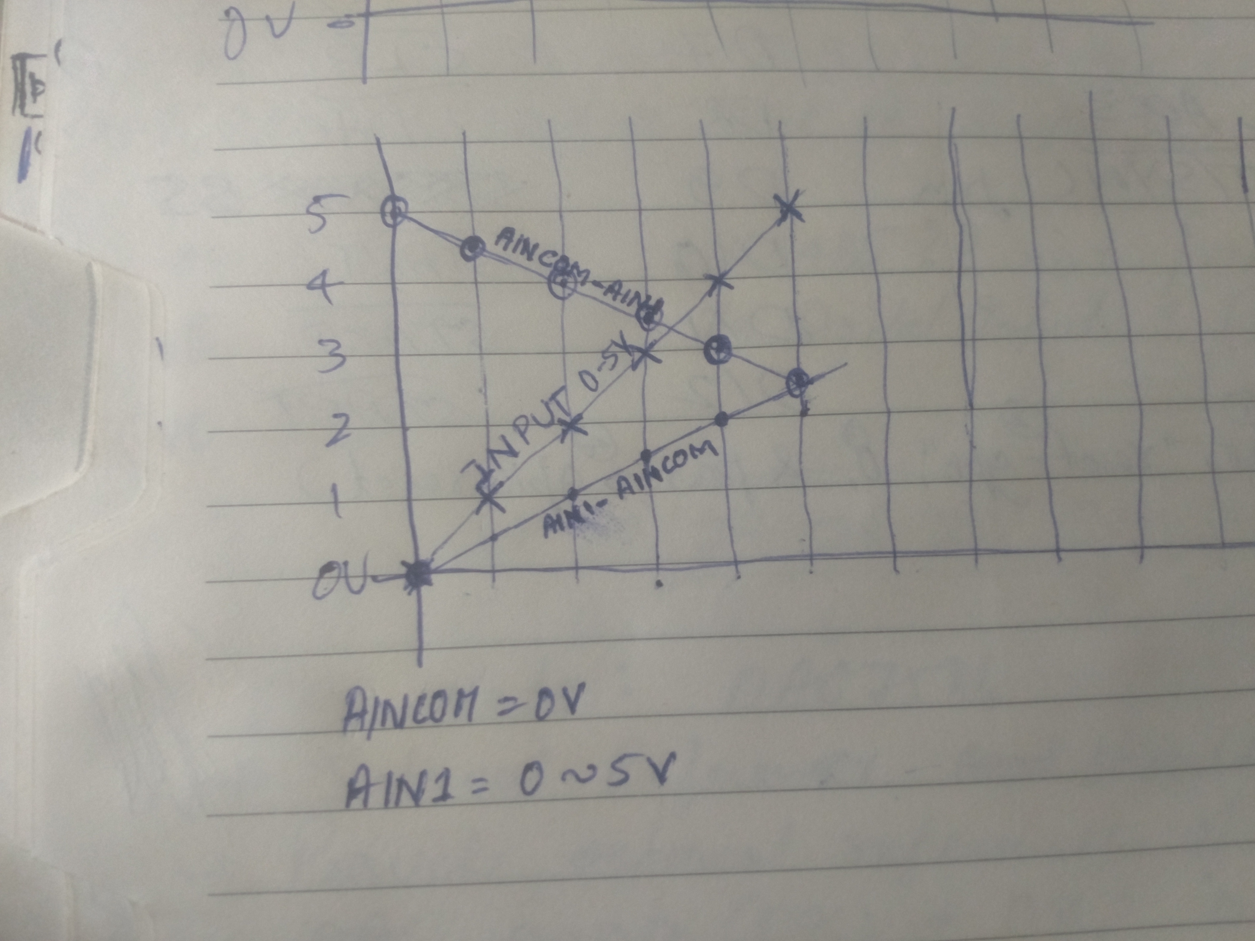
AVDD = 5V, AVSS=0V, AINCOM=0V, AIN1= 0-5V potentiometer 

All register are at their reset value other than the below registers.

Reg 0x00 = 0x00(clr flags), Reg 0x04 = 0x3C(2k sps)

When Reg 0x02 is fed with 0xC1 value, I am getting 5V(0xFFFF) to 2.5V(0x81C3) adc variation for 0V to 5V input at AIN1.

When Reg 0x02 is few with 0xC1 value, I am getting 0V(0x0000) to 2.5V(0x81C3) adc variation for 0V to 5V input at AIN1.

I need to configure the adc values to vary from 0V(0x0000) to 5V(0xFFFF) for 0V to 5V variation at AIN1.

Please guide me in finding the issue here. Thank you

  • Hi Vik,

    The output of the ADS114S08 is binary 2's complement. Negative full-scale is 0x8000 and 0xFFFF is a -1 code (one less than zero). There are a couple of ways you can make the measurement. One is to use just the positive scale and use a 5V reference. The second method is to make a differential measurement where you set AINCOM to 2.5V, and you connect the pot to AIN1 and AGND. For this case a 0 reading would be 2.5V, so you would have to do some math computations.

    Let me know which method you would prefer and I can tell you how to set it up on the EVM.

    Best regards,
    Bob B
  • Hi Bob,

    Thank you for your reply, I think I tried your method 1 to measure in the positive scale with REFP0=5V, REFN0=0V. But for 0 to 5V variation at AIN1, I get 0x0000 to 0x8000 Half scale ADC output.

    Is it possible to get the single end measurement of 16bit Full scale ADC value for 0V(0x0000) to 5V(0xFFFF)??
  • Hi Vik,

    As I stated previously, the ADS114S08 is a differential measurement and outputs the conversion result in binary two's complement.  Half of the output codes are in the positive direction (0x0000 to 0x7FFF) and half are in the negative direction (0xFFFF to 0x8000).  0xFFFF is -1 not positive full-scale.  The ADS114S08 does not allow for the type of measurement you are requesting directly.

    To recapture the use of all 16 bits, you can set AINCOM to 2.5V by changing the jumper JP13 to VREF (2-3).  The input voltage at AIN1 above 2.5V will output positive codes, and below 2.5V will output negative codes.  For this case you would want to use the 2.5V reference to get the best resolution.  To the conversion result you would add 2.5V.  For example, a 0V input at AIN1 would produce an output of -2.5V (negative full-scale of 0x8000) and you would add 2.5V to get the proper result of 0V.  An input of 2.5V at AIN1 would have a differential input of 0V and the conversion result would also be 0.  Add to this 2.5V, and you would get 2.5V as the result.  This works for all input values up to 5V.

    Best regards,

    Bob B

  • It works now. I selected and enabled the internal 2.5V ref and connected it to AINCOM from REFOUT. Now I get a neat 16bit 2's compliment variation for 0V to 5V at AIN1.

    Thank you Bob. :) cheers!!