This thread has been locked.

If you have a related question, please click the "Ask a related question" button in the top right corner. The newly created question will be automatically linked to this question.

ADS1299: Data Rate is down shifting from 250 SPS to 62 SPS and sometimes 0 SPS

Part Number: ADS1299

Hello!

I love the ADS1299 a lot, and im excited to build some new hardware with it.

However I keep running into a strange problem and I've been trying to figure it out for  a couple of weeks now!

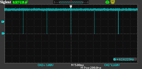
Here you see the DRDY pin being toggled at 62 SPS instead of the 250 that it should be toggling at. I've been streaming and see the data rate go back up to the 250, but this down ot 62 (which is 250/4) is an intermittent problem.

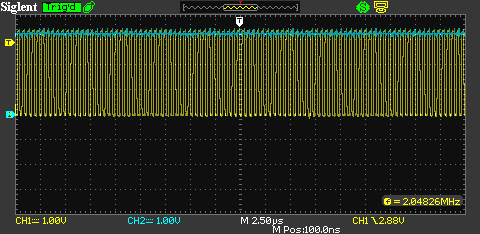
I figured that I should check the ADS1299 output pin and say that it's clock it accurate at the 2.049 MHz.

I'll attach my schematic too

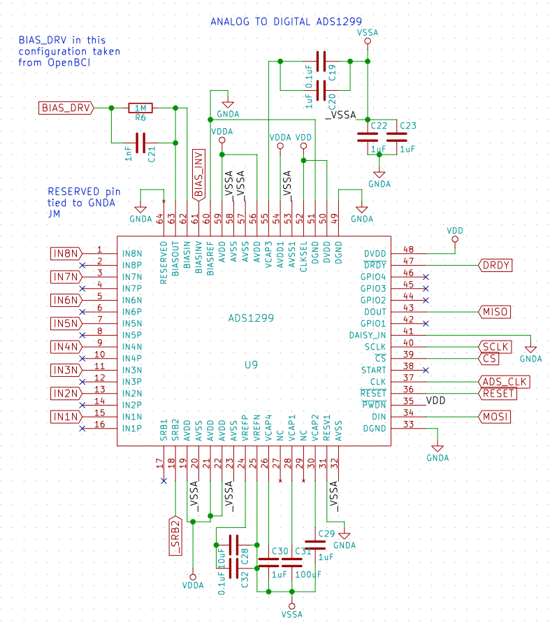
It's copied from the OpenBCI.

  • Hi Andrew,

    Thanks for your post, and welcome to our forum!

    Can you please read back all of the register settings? If you could list them in a hexadecimal format, I can do a quick review to see if anything is not set correctly. 250 SPS should be the minimum data rate in this device with a 2.048 MHz clock. Thanks for verify that the internal oscillator is working properly!

    Are you communicating with the device at all when you probe the /DRDY pin? Please note that the falling edge of SCLK will clear /DRDY. This may change the time between /DRDY rising edges (depending on when SCLK begins to toggle), but the period between /DRDY falling edges should always match the configured output data rate.

    Best Regards,

  • Hi Ryan,

    Thank you so much for the welcome! I have been using the ADS1299 for over three years and this is my first post, so good job!

    Register settings:
    Board ADS Registers
    ADS_ID, 00, 3E, 0, 0, 1, 1, 1, 1, 1, 0
    CONFIG1, 01, 96, 1, 0, 0, 1, 0, 1, 1, 0
    CONFIG2, 02, C0, 1, 1, 0, 0, 0, 0, 0, 0
    CONFIG3, 03, EC, 1, 1, 1, 0, 1, 1, 0, 0
    LOFF, 04, 00, 0, 0, 0, 0, 0, 0, 0, 0
    CH1SET, 05, 68, 0, 1, 1, 0, 1, 0, 0, 0
    CH2SET, 06, 68, 0, 1, 1, 0, 1, 0, 0, 0
    CH3SET, 07, 68, 0, 1, 1, 0, 1, 0, 0, 0
    CH4SET, 08, 68, 0, 1, 1, 0, 1, 0, 0, 0
    CH5SET, 09, 68, 0, 1, 1, 0, 1, 0, 0, 0
    CH6SET, 0A, 68, 0, 1, 1, 0, 1, 0, 0, 0
    CH7SET, 0B, 68, 0, 1, 1, 0, 1, 0, 0, 0
    CH8SET, 0C, 68, 0, 1, 1, 0, 1, 0, 0, 0
    BIAS_SENSP, 0D, FF, 1, 1, 1, 1, 1, 1, 1, 1
    BIAS_SENSN, 0E, FF, 1, 1, 1, 1, 1, 1, 1, 1
    LOFF_SENSP, 0F, 00, 0, 0, 0, 0, 0, 0, 0, 0
    LOFF_SENSN, 10, 00, 0, 0, 0, 0, 0, 0, 0, 0
    LOFF_FLIP, 11, 00, 0, 0, 0, 0, 0, 0, 0, 0
    LOFF_STATP, 12, 00, 0, 0, 0, 0, 0, 0, 0, 0
    LOFF_STATN, 13, 00, 0, 0, 0, 0, 0, 0, 0, 0
    GPIO, 14, 0F, 0, 0, 0, 0, 1, 1, 1, 1
    MISC1, 15, 00, 0, 0, 0, 0, 0, 0, 0, 0
    MISC2, 16, 00, 0, 0, 0, 0, 0, 0, 0, 0
    CONFIG4, 17, 00, 0, 0, 0, 0, 0, 0, 0, 0


    Are you communicating with the device at all when you probe the /DRDY pin?

    Yes whether i am communicating or not has no effect.

    Please note that the falling edge of SCLK will clear /DRDY. This may change the time between /DRDY rising edges (depending on when SCLK begins to toggle), but the period between /DRDY falling edges should always match the configured output data rate.

    Okay!
  • If i run at 1000Hz, then the sample rate goes up to 255Hz but is rather unstable and fluctuates all the way down to 220Hz.
  • Looks like my ADS1299 register settings are changing all the time... this seems like a probable cause?

    After my start up
    Board ADS Registers
    ADS_ID, 00, 0E, 0, 0, 0, 0, 1, 1, 1, 0
    CONFIG1, 01, FF, 1, 1, 1, 1, 1, 1, 1, 1
    CONFIG2, 02, F6, 1, 1, 1, 1, 0, 1, 1, 0
    CONFIG3, 03, 0F, 0, 0, 0, 0, 1, 1, 1, 1
    LOFF, 04, FF, 1, 1, 1, 1, 1, 1, 1, 1
    CH1SET, 05, D6, 1, 1, 0, 1, 0, 1, 1, 0
    CH2SET, 06, DC, 1, 1, 0, 1, 1, 1, 0, 0
    CH3SET, 07, FF, 1, 1, 1, 1, 1, 1, 1, 1
    CH4SET, 08, C6, 1, 1, 0, 0, 0, 1, 1, 0
    CH5SET, 09, 94, 1, 0, 0, 1, 0, 1, 0, 0
    CH6SET, 0A, FF, 1, 1, 1, 1, 1, 1, 1, 1
    CH7SET, 0B, BE, 1, 0, 1, 1, 1, 1, 1, 0
    CH8SET, 0C, A9, 1, 0, 1, 0, 1, 0, 0, 1
    BIAS_SENSP, 0D, 0E, 0, 0, 0, 0, 1, 1, 1, 0
    BIAS_SENSN, 0E, FF, 1, 1, 1, 1, 1, 1, 1, 1
    LOFF_SENSP, 0F, DD, 1, 1, 0, 1, 1, 1, 0, 1
    LOFF_SENSN, 10, D6, 1, 1, 0, 1, 0, 1, 1, 0
    LOFF_FLIP, 11, FF, 1, 1, 1, 1, 1, 1, 1, 1
    LOFF_STATP, 12, CE, 1, 1, 0, 0, 1, 1, 1, 0
    LOFF_STATN, 13, 4E, 0, 1, 0, 0, 1, 1, 1, 0
    GPIO, 14, FF, 1, 1, 1, 1, 1, 1, 1, 1
    MISC1, 15, C3, 1, 1, 0, 0, 0, 0, 1, 1
    MISC2, 16, 00, 0, 0, 0, 0, 0, 0, 0, 0
    CONFIG4, 17, FF, 1, 1, 1, 1, 1, 1, 1, 1

    After a reset to my default channel settings
    Board ADS Registers
    ADS_ID, 00, 3E, 0, 0, 1, 1, 1, 1, 1, 0
    CONFIG1, 01, 96, 1, 0, 0, 1, 0, 1, 1, 0
    CONFIG2, 02, C0, 1, 1, 0, 0, 0, 0, 0, 0
    CONFIG3, 03, 60, 0, 1, 1, 0, 0, 0, 0, 0
    LOFF, 04, 00, 0, 0, 0, 0, 0, 0, 0, 0
    CH1SET, 05, 68, 0, 1, 1, 0, 1, 0, 0, 0
    CH2SET, 06, 68, 0, 1, 1, 0, 1, 0, 0, 0
    CH3SET, 07, 68, 0, 1, 1, 0, 1, 0, 0, 0
    CH4SET, 08, 68, 0, 1, 1, 0, 1, 0, 0, 0
    CH5SET, 09, 68, 0, 1, 1, 0, 1, 0, 0, 0
    CH6SET, 0A, 68, 0, 1, 1, 0, 1, 0, 0, 0
    CH7SET, 0B, 68, 0, 1, 1, 0, 1, 0, 0, 0
    CH8SET, 0C, 68, 0, 1, 1, 0, 1, 0, 0, 0
    BIAS_SENSP, 0D, FF, 1, 1, 1, 1, 1, 1, 1, 1
    BIAS_SENSN, 0E, FF, 1, 1, 1, 1, 1, 1, 1, 1
    LOFF_SENSP, 0F, 00, 0, 0, 0, 0, 0, 0, 0, 0
    LOFF_SENSN, 10, 00, 0, 0, 0, 0, 0, 0, 0, 0
    LOFF_FLIP, 11, 00, 0, 0, 0, 0, 0, 0, 0, 0
    LOFF_STATP, 12, 00, 0, 0, 0, 0, 0, 0, 0, 0
    LOFF_STATN, 13, 00, 0, 0, 0, 0, 0, 0, 0, 0
    GPIO, 14, EF, 1, 1, 1, 0, 1, 1, 1, 1
    MISC1, 15, 00, 0, 0, 0, 0, 0, 0, 0, 0
    MISC2, 16, 00, 0, 0, 0, 0, 0, 0, 0, 0
    CONFIG4, 17, 00, 0, 0, 0, 0, 0, 0, 0, 0

    Another one after streaming
    Board ADS Registers
    ADS_ID, 00, 3E, 0, 0, 1, 1, 1, 1, 1, 0
    CONFIG1, 01, 96, 1, 0, 0, 1, 0, 1, 1, 0
    CONFIG2, 02, C0, 1, 1, 0, 0, 0, 0, 0, 0
    CONFIG3, 03, 60, 0, 1, 1, 0, 0, 0, 0, 0
    LOFF, 04, 00, 0, 0, 0, 0, 0, 0, 0, 0
    CH1SET, 05, 68, 0, 1, 1, 0, 1, 0, 0, 0
    CH2SET, 06, 68, 0, 1, 1, 0, 1, 0, 0, 0
    CH3SET, 07, 68, 0, 1, 1, 0, 1, 0, 0, 0
    CH4SET, 08, 68, 0, 1, 1, 0, 1, 0, 0, 0
    CH5SET, 09, 68, 0, 1, 1, 0, 1, 0, 0, 0
    CH6SET, 0A, 68, 0, 1, 1, 0, 1, 0, 0, 0
    CH7SET, 0B, 68, 0, 1, 1, 0, 1, 0, 0, 0
    CH8SET, 0C, 68, 0, 1, 1, 0, 1, 0, 0, 0
    BIAS_SENSP, 0D, FF, 1, 1, 1, 1, 1, 1, 1, 1
    BIAS_SENSN, 0E, FF, 1, 1, 1, 1, 1, 1, 1, 1
    LOFF_SENSP, 0F, 00, 0, 0, 0, 0, 0, 0, 0, 0
    LOFF_SENSN, 10, 00, 0, 0, 0, 0, 0, 0, 0, 0
    LOFF_FLIP, 11, 00, 0, 0, 0, 0, 0, 0, 0, 0
    LOFF_STATP, 12, 00, 0, 0, 0, 0, 0, 0, 0, 0
    LOFF_STATN, 13, 00, 0, 0, 0, 0, 0, 0, 0, 0
    GPIO, 14, EF, 1, 1, 1, 0, 1, 1, 1, 1
    MISC1, 15, 00, 0, 0, 0, 0, 0, 0, 0, 0
    MISC2, 16, 00, 0, 0, 0, 0, 0, 0, 0, 0
    CONFIG4, 17, 00, 0, 0, 0, 0, 0, 0, 0, 0
  • Hi Andrew,

    Are you issuing an extra /RESET pulse after power-up? After both analog and digital supplies are established, we generally recommended that you wait for some time (tPOR) and then issue an additional /RESET pulse (or RESET command) to ensure the internal one-time programmable registers from the factory are read correctly. I say this because some of the bits you read back after start up should never be set the way they are (typically listed as Reserved in the register map). Once the reset is done, you should be able to write your own register values and they should never change on their own.

    Also, are you remembering to exit Read Data Continuous Mode by sending the SDATAC command before any other SPI commands?

    I know that you checked on the internal clock before, but please configure the CLK pin to output the internal oscillator and just keep an eye on it periodically with a scope to ensure it is not changing momentarily.


    Best Regards,

  • Hi Andrew,

    Were you able to figure out why your data rate was changing?

    Regards,