This thread has been locked.

If you have a related question, please click the "Ask a related question" button in the top right corner. The newly created question will be automatically linked to this question.

DAC7760: DAC7760 parallel output design feasibility

Part Number: DAC7760


Dear Data Convert Team:

 I need two kinds of drive attribute sensors. because of It's added Iout and voltage driver, the soft control mode have 2 cases.

A. The single DAC7760  Iout and Vout;

Will the voltage and current of the pouring power burn the other DAC7760?

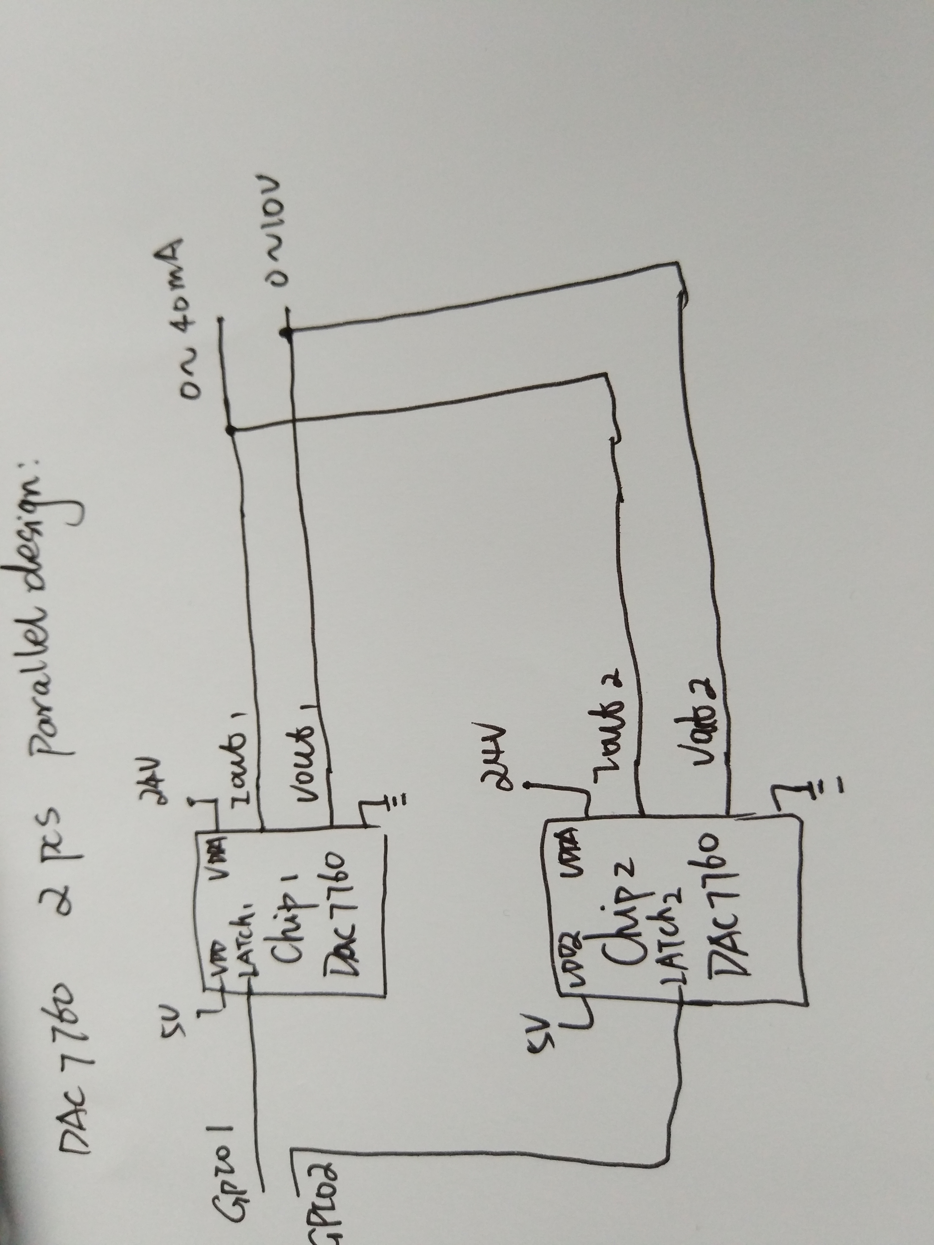
B. The 2pcs DAC7760  meanwhile output Iout or Vout .

Is the 2pcs DAC7760  electric current loop at the same time output 0~40mA?

Thanks

meanwhile

  • Hi Eric,

    I believe this configuration is okay for the current output mode, but tying the Vout lines together can be problematic. As all DACs for gain, offset, and linearity error the voltages on the pins would not be same, meaning that current would flow between the DACs. The worst case would be if the DACs do not latch to the same value (DAC1 =10V and DAC2 = 0V) where they would likely source their short circuit current into each other. If you were to add resistor in series with each output, say 25-50Ω, then the current flowing between the DACs would be limited when there is a voltage difference.

    Thanks!
    Paul
  • Dear Paul:

    There is no problem with the parallel current output.

    For parallel Voltage, I select that the DAC7760 Vout is series diode.It’s Used for reverse cut-off voltage,and no loss of output drive capability. Is it feasible?

    Thanks a lot!

    feasible

  • Hi Eric,

    That is a feasible solution, though if you are trying to get a higher current output capability for the VOUT, you could consider using one channel only and an output buffer.

    Thanks!
    Paul
  • Hi Eric,

    Adding a series diode to the output should protect the Vout pins on the two devices. But this will cause voltage drop due to the forward voltage of each diode. I suppose you could connect Vsense+ on the cathode side of the diodes to compensate for the voltage drop. I'm not sure how the devices will behave if both of their Vsense+ pins are connected to the same node. There will be small voltage differences between the two devices even if they are set to the same code. Since both are trying to regulate the voltage to a slightly different value, this could cause a situation where they are kind of "fighting' each other and may even lead to some sort of oscillation. You may want to test this with a couple of EVMs as this is definitely not a typical use case for the device.

    Thanks,
    Garrett