This thread has been locked.

If you have a related question, please click the "Ask a related question" button in the top right corner. The newly created question will be automatically linked to this question.

initial flow at power up figure 64 of ads1298 data sheet might be wrong

Other Parts Discussed in Thread: ADS1298

initial flow at power up figure 64 of ads1298 data sheet might be wrong.

Stop read data continuos is set so registers can be writen .

if start is brought high before the start continous conversion a conversion may complete before the SDATAC continous conversion command is sent.

shouldn;t continous conversions be set then all the data out would happen at a consistant frequency?

Also data may be clocked out whale that data is clocked in then where a conversion data starts or ends could be confusing.

// SDATAC Command so Registers can be Written

start conversion by start going HIGH

// Put the Device Back in RDATAC Mode


  • Josh,

    The flow chart was written based on the assumption that you would be using an interrupt on your micro that monitored the DRDY output.  If the RDATAC command is sent directly after the START pin when high, generally speaking there would be plenty of time to accomodate the first DRDY pulse.  Any data that is clocked out during the RDATAC command should be ignored.

    After the device is configured and START is set high, the DRDY will output a pulse at a continuous frequency (depending on the register settings and clock frequency).  Data reads should be started with the active DRDY pulse and end when you have all conversion results based on the number of active channels.  Data reception must be completed before the next DRDY output pulse goes active.

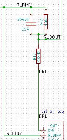
  • Now I want to have a multiple device setup with DRL

    I set all pins to effect DRL

    RLD_SENSP    0    b1111 1111        all bits effect RLD
    RLD_SENSN    0    b1111 1111        all bits effect RLD

    is that correct? For a basic testing I would hook this to all the pos. or neg. inputs and hook them up to a function generator pos to one side neg to another to create a wave for the system to mesure?

    RLDINV is common on all ads1298 modules.

    I am referencing page 62,63,60 with the patent protection resistor.


    What kind of test setup documentation should I be looking at? Or what documentation would you sugjest how would you test this it a white breadboard?

  • I was thinking of taking the end off some ear buds and using my mp3 player as a function generator to test this out.

    I would mesure with a metter 1v p-p that should be safe by adjusting the volume then lock the keypad on my mp3 player it is a little sandisk and use audacity in linux a sound editing program to make sine wave MP3 and other waves to mesure with the ads1298.

    I thought a 1k resistor or some setting would work any sugjestions to keep it safe with the ads1298 or if I found a function generator used any sugjestions their is the 100k patent protection resistors on every input pin of the ads1298. Fallowing the data sheet.