This thread has been locked.

If you have a related question, please click the "Ask a related question" button in the top right corner. The newly created question will be automatically linked to this question.

DAC7760: Power up requirements

Part Number: DAC7760


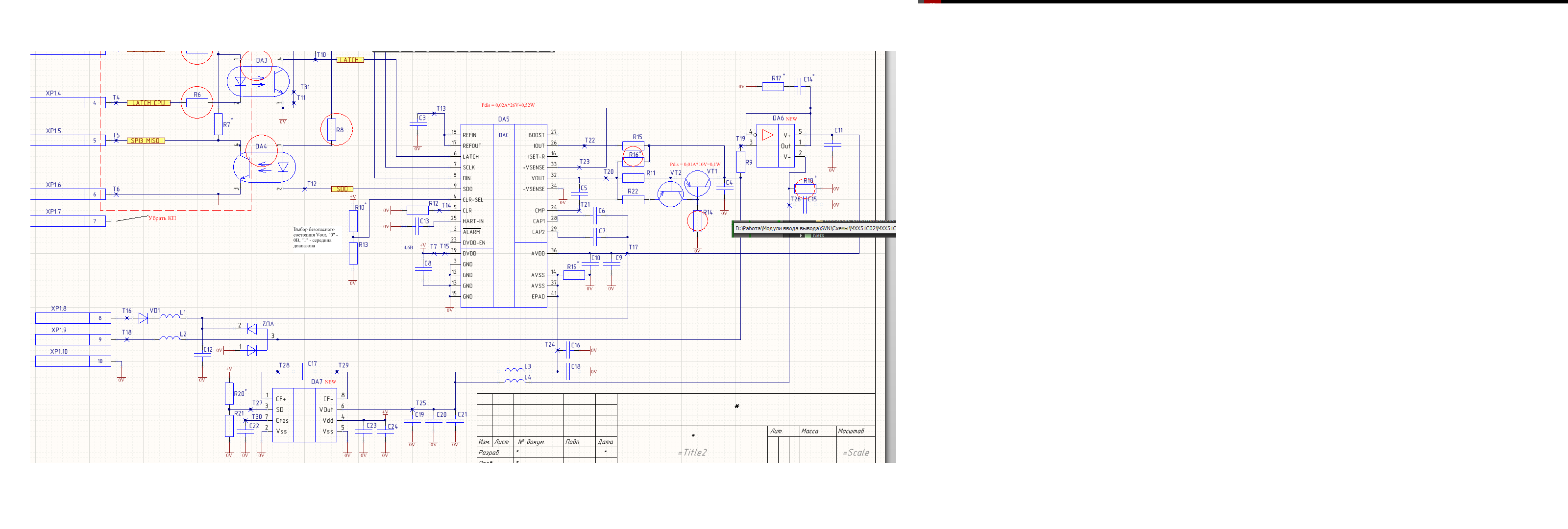
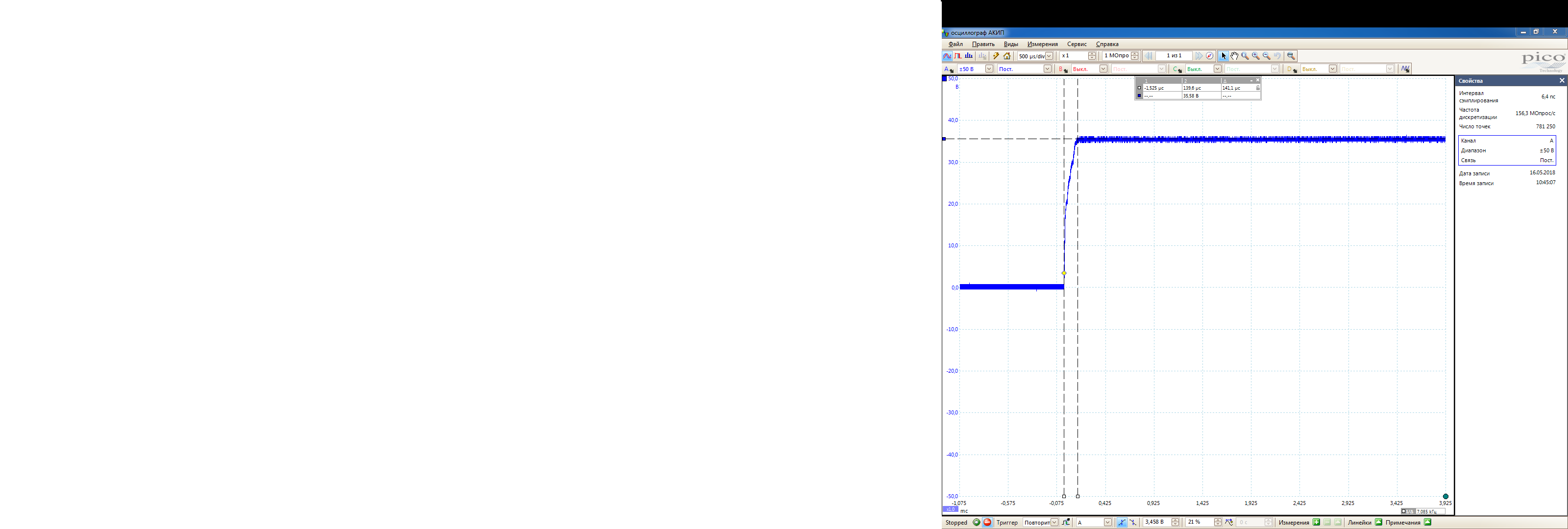
We have very strange behavior when powering DAC7760 from 36Vin (AVDD = 36V, AVSS = GND).

DAC has burned every time until we inserted 5 Ohm resistor in power supply circuit between 36V and AVDD. After it all works fine.

We don't seen any special requirements for power up in datasheet. So we have some doubts why it happens.

After DAC has burned we see 50 Ohm between AVDD and AVSS. All other pins looks good.

It's need to be pointed that AVSS looks fine in any case (there are no spikes, voltage are 10% lower than absolute maximum ratings).

What TI can recommend in this case? 5 Ohm resistor is not pretty good solution.

  • Hi Vladimir,

    Can you provide a schematic for this? It seems strange that adding a series 5 ohm between the supply and AVDD would cause device failure. Is this resistor for current limiting in case of fault?

    Thanks,
    Garrett
  • Hello. I'm customer, who have this problem. Vladimir asked me to send schem. Fault happens when no any currentlimiting resistor. In this circuit I don't use DA7, instead of it there is R19. C23 is 10uF, but it doesn't influence on the problem, because I deleted it and fault happened whatever. Currentlimiting resistor was put instead of L1

  • Hi Denis,

    Welcome to the E2E forums!

    Does this occur immediately when power is applied or after the DAC has been programmed to some state? 

    I'm wondering if L1 is coupling with the capacitors causing an LC response that could cause overshoot and ringing, especially if the rise time of the power supply is short.

    1. If you replace L1 with a 0 ohm resistor instead of 5 ohm does the device still get damaged?

    2. Can you measure the voltage waveform at the AVDD device pin during start up? I want to see if there is overshoot that could damage the device.

    3. Does this occur if you use a lower voltage? A slower rise time for the power supply may help if this is the issue.

    Thanks,

    Garrett

  • The fault occurs immediately after applying power. L1 isn't an nductor, it's a ferrit bead (FB0603-0,2A-2500Ohm (100MHz)-25%-0,8Ohm).

    1. Replacing L1 by 0Ohm doesn't solve the problem

    2. There are interesting cases. Before I looked at this voltage in moment of switch on. Diagrams didn't have any spike, overshoot. Now, with the first sample diagrams were good. They are below

      This is small step which is on reason of C23 - 10uF

    This is without C23. 

    Beacause of I coudn't make DAC default, I took other sample

    Diagram on it was below

    There is overshooting. The both sample are identical, and there were DAC fault on both of them before, I had replaced DAC on both of them. 

    I cheked other samples and found that more part of them had overshooting. I found that reason was VD1. How I understand, some of diodes have degradated, and their resistances have increased. There aren't any overshooting in this case. And visa virsa there is a spike when diode isn't degradated. So decision of problem is putting resistor seriesly to L1. It'll do no degradation of VD1 and fault of DAC.

    3. Lower voltage of power supply and slow rise time (softstart) of it doesn't make the fault. Fault happens only when I put power supply, which has been switched on earlier, and voltage of it is 36V.

  • Hi Denis,

    I suspect that this overshoot is causing damage to the device. It looks like the one you show is less than the absolute maximum rating for the AVDD pin, but some may be greater depending on rise time.

    The cause of this is some LC combination with a small resistance. This could include parasitic values from the PCB and even the ferrite beads will provide inductance if the frequency is high. When you add a small series resistor you will reduce the quality factor and damp out the overshoot and oscillation. Using a series resistor should be an okay solution since even with the 5 ohm the power dissipation will be small. Reducing the capacitance at the AVDD net should also help reduce overshoot.

    Are you sure you are referring to C23 in the above post? I thought you said you didn't use DA7 and this is connected there.

    Another option is to control the slew rate so the edge is not fast enough to cause overshoot and ringing.

    Thanks,
    Garrett
  • Hi Garrett. C23 is on board. Thanks for your answers. The problem is resolved, so it can be closed.

    Thanks,

    Denis.