This thread has been locked.

If you have a related question, please click the "Ask a related question" button in the top right corner. The newly created question will be automatically linked to this question.

ADS131A04: F28069

Part Number: ADS131A04

Greetings!

I am using ADS131A04 connecting with F28069. I followed the setup guide in the datasheet of ADS131A04. I set up the M0, M1, and M2 as following:

M0 - IOVDD: Asynchronous interrupt mode

M1 - IOVDD: 32 bit SPI word transfer size (while F28069 can only support at most 16 bit SPI transfer size.)

M2 - GND: Hamming code word validation off

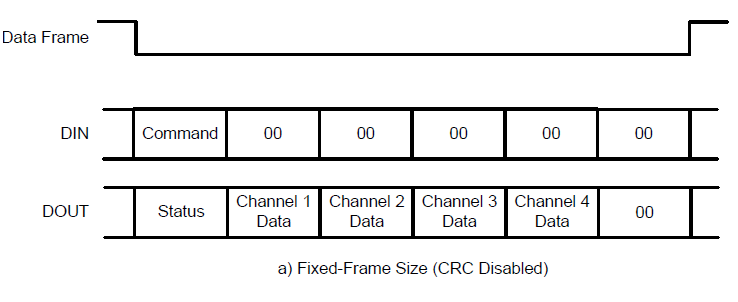
I use the fixed frame size with 4 ADCs enabled. I follow the instruction of Figure 51 on Page 36 of ADS131A04 data sheet. However, I have several questions on the communication between two devices:

1. On Figure 51, I shows at the beginning of data transfer, the DIN pin should have "command". What command does this refer to? I don't find the corresponding command for data acquisition, so I send "Null" command.

2. Figure 51 indicates that every data frame should contains 6 * 32 bit data for fixed frame size setup. However, I have to transfer another 16 bit data before receiving the data frame. Below is the pseudocode that I write:

Temp = ADS131A04Receive16();
dFrame->status = ADS131A04Receive32();

for (i = 0; i < 4; i++) {
dFrame->ch[i] = ADS131A04Receive32();
}

crc = ADS131A04Receive32();

I don't know why I have to do this.

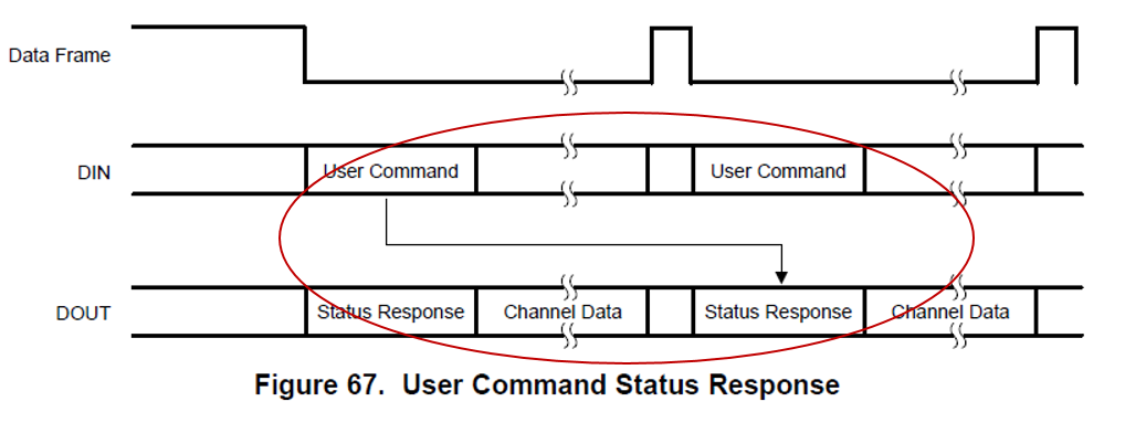
3. Figure 67 on Page 49 of ADS131A04 data sheet confuses me. Why would the response corresponds to previous command? Does this conflict with Figure 51?

Thanks,

Dan

  • Hi Dan,

    Thanks for your post. Just a quick note: I believe you are using an older version of the datasheet, so the figure and page numbers don't quite line up with your question. Please check the product page for the latest revision (SBAS590D). I assume your first question is referring to this figure below (Figure 54 in the updated datasheet):

    1. Sending the NULL command is fine during normal data acquisition. The corresponding STATUS word on DOUT will tell you the contents of the STAT_1 register so that you can monitor for general fault updates.
    2. I'm not sure what you mean here by sending "another 16 bits" before the data frame. Are you referring to the STATUS word length? All STATUS words are 16-bits and must be padded with zeroes at the end to match the data word size you've configured.
    3. The command status response waits until the entire command is sent and decoded, so it is sent in the next data frame. It does not conflict with the other figure.

    Best Regards,

  • Hi Ryan,

    Thanks very much for your reply. Yes, I was referring that figure.

    For the second question, please check the pseudocode. In function "ADS131A04Receive16()", F28069 sends 16 bits of 0 to ADS131A04 and receives the response from ADS131A04. Function "ADS131A04Receive32()" just implements "ADS131A04Receive16()" twice. In this way, the channel data can be read correctly. It seems that there is a 16 bits data shift lag of SPIRX than SPITX. I don't know why this happens.

    For the third question, I am wondering if all ADCs are enabled, ADS131A04 will reply a whole data frame containing channel data on receiving whatever command? Even if F28069 just sends a command to read register value, for example, CLK1 Register, ADS131A04 will reply the register value and also the channel data?

    Thanks,
    Dan
  • Hi Dan,

    How did you find that the extra 16-bits needed to be sent? I don't expect the device to behave this way - you should only be sending 6x 32-bit words to the ADS131A04 in each data frame. Can you show me a logic analyzer or oscilloscope capture for a single data frame?

    Best Regards,
  • Hi Ryan,

    I find that in the scenario without those extra 16-bits, the channel data received by F28069 has 0 for the whole lower 16 bits. After adding those extra 16 bits, the channel data received is reasonable. I will do a oscilloscope test, but I need some time. Once I get the plots, I will show you.

    Thanks,

    Dan 

  • Hi Ryan,

    I used a oscilloscope to check the data frame. I found that at the beginning of data frame communication, the procedure works like this:

    1. F28069 sends NULL to ADS131A04

    2. ADS131A04 sends STAT_1 data back

    3. SPI RX buffer of F28069 receives the STAT_1 (the status) data. However, the data in the RX buffer does not pass to the returning variable in the function.

    4. F28069 sends another NULL to ADS131A04

    5. ADS131A04 sends a 16-bit 0 back to F28069 to accomplish the 32-bit words.

    6. SPI RX buffer of F28069 receives the 16-bit 0. However, at this time STAT_1 (the status) data was passed to the returning variable in the function.

    I think this results in the 16-bit shift. I don't know why the SPI RX buffer gets the data but does not pass to the variable until the next data transfer.

  • Hi Dan,

    Thanks for the update. Let me try to clarify a few details:

    1. Steps 1 and 2 should occur simultaneously, where the STAT_1 contents are in reference to the NULL command that was sent at the beginning of the previous data frame. You should have seen this on the scope. Please attach a scope image of SCLK, DIN, and DOUT if you would like us to review it.
    2. Step 4 - is this referring to the same data frame at Steps 1 and 2? Understand that the ADS131A04 will not necessarily recognize this as a second NULL command, but rather an additional 16 zeroes to complete the first 32-bit word in the data frame. In other words, the Command Status Response will only be given for the first 16 zeroes on DIN. I believe you understand that, but just wanted to be clear.
    3. Step 5 - your SPI RX buffer stores the STAT_1 contents from Step 2 into memory while the "second NULL command" is sent in Step 4.

    After the first word is complete (NULL + 0x0000), you should continue to send 5 more 32-bit words (all zeroes) to the ADS131A04 in order to read the rest of the data in the data frame. Are you able to do that and read valid data?

    Best Regards,

  • Hi Ryan,

    Thanks very much for your help and time. We have figured out the problem. It was the communication between ADS131A04 and F28069. The data in the SPI RX buffer was not shifted in time. We delayed around 30 ns in every data transformation, and the problem was solved.

    Regards,

    Dan