This thread has been locked.

If you have a related question, please click the "Ask a related question" button in the top right corner. The newly created question will be automatically linked to this question.

ADS1256: Multiple ADC synchronization with SYNC pin is not working

Part Number: ADS1256


We have to measure magnetic field of a magnet , where each axis data will be taken from each adc

To measure X- axis - X channel is connected to one ADS1256

To measure Y- axis - Y channel is connected to other ADS1256

To measure Z- axis - Z channel is connected to one more ADS1256

As we need to measure accurate magnetic field, all the ADC'S SYNC pin are connected to one IO pin and we are doing sync once after power on.

Test procedure:

Same magnetic field is generated on all ADC'S.

Software reading process:

Generate SYNC

Sending RDATAC command to all ADC's and inside DRDY interrupt of X and we are reading the data of X,Y,Z 

But when see the data there is a phase shift of values captured n X,Y,Z

There is 5-6 samples reading difference on each Axis.

So what might be the issue..?

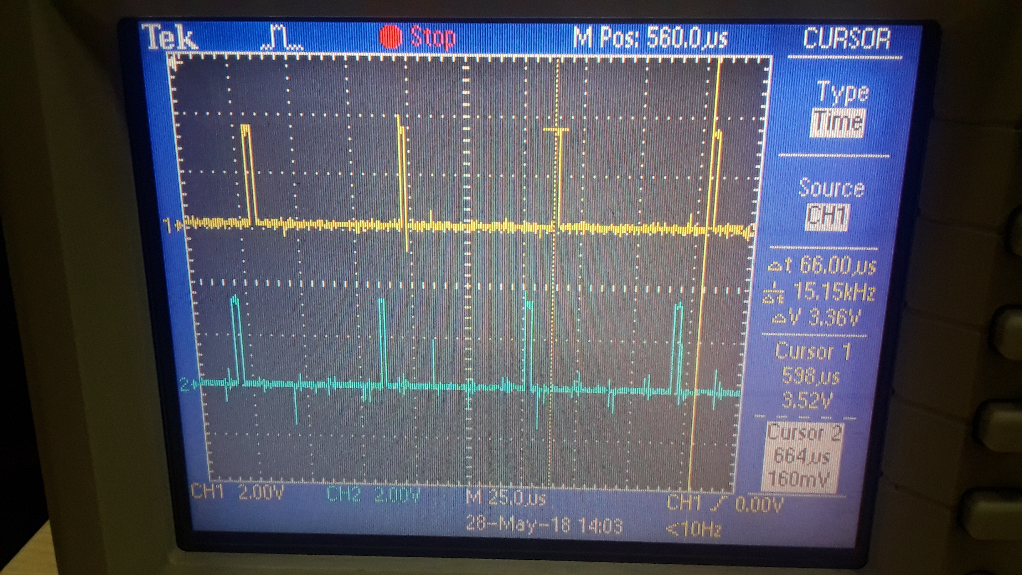
Note:If we see DRDY pin of X, it is always constant (pulse ON and OFF timing)

If we see DRDY pin of Y,Z, it is not constant (changing gradually)

  • Hi Sreenath,

    Welcome to the TI E2E Forums! Would you be able to share a schematic of your circuit?

    Have you performed any offset and gain error calibration on the ADCs?
    If you are seeing a difference between each ADC's output code and are sure the inputs signals to each ADC are the same, then the difference may likely be explained by either an offset or gain error. Performing system offset and gain calibration (note: this is not the same as self-calibration) is likely needed to make all ADC result match. If by "5-6 samples reading difference" you mean the output codes differ by 5-6 counts, then this would certainly be well within the ADS1256's typical offset/gain error tolerance.

    Regarding the /DRDY period of the Y & Z axis...
    How are these ADC's clocked? Is there a single external clock source shared between all ADC's or does each ADC connect to its own crystal? If the clocks are independent of one another, then you might be seeing the /DRDY period drift proportionally the crystal's frequency of oscillation; however, I'm not sure how large of change you're seeing to know if the crystal tolerance is large enough to explain this effect. Ifyou have an oscilloscope or logic analyzer screenshot of this changing /DRDY period, that would be helpful.

    Note: The "RDATAC" command only needs to be issued once, before you start continuously collecting data. Therefore, you could issue this command outside of the /DRDY interrupt. Also, when configuring the ADS1256, I recommend always issuing the "SDATAC" command before any "WREG" commands to ensure that the ADC is not in RDATAC mode (where WREG commands are ignored).

    I hope that helps,
    Chris
  • Hi Christopher Thanks for the reply,

    1.We are using different crystals(clock sources) for each ADC with same frequency(7.8 MHZ).

       But any way after device power on , we are making SYNC pin low to high , which actually synchronizes all ADC's at same time.

       If any thing i missed please suggest...?

    2.Attached DRDY signal of two ADC's at sample rate of 15K.

       If we check those signals, gradually DRDY signal shifts.

       So can you please suggest me the cause for  these issue (DRDY signal shift)......?

       DRDY signal shift:

       Gradually CH2 signal shifts to left side

  • Hi sreenath,

    1. When using separate crystals it's possible that these clocks are out of phase. When you issue the SYNC pulse, the actual SYNC operation will occur on one of the next internal clock edges. In this case the ADC's will be nearly synchronized, likely with 1-2 clock periods, which shouldn't be an issue...

    2. If I understand correctly, all of the /DRDY pulses line up after toggling the SYNC pin, but then after some time (several minutes?), you see that the /DRDY pulses are no loner synchronized, is that correct?

      If so, then most likely this is due to the slight differences in the crystal oscillation frequencies (notice that the yellow /DRDY period is 15.15kHz, which is 1% error). Unfortunately, it might not easy to resolve this issue. The possible solutions I see to this issue would be...

      1. (Easiest solution) You periodically issue the SYNC pulse to re-synchronize the devices. This will momentarily realign the /DRDY pulses, but this process will need to be repeated every so often to ensure the /DRDY pulses never drift apart beyond some acceptable limit.

      2. (BOM change) You could try tuning the crystals slightly by adjusting the load capacitance values. The crystals frequency of oscillation can be "pulled" as you adjust the load capacitance; however, this would be a very manual approach and the required load capacitance would be slightly difference for every crystal.

      3. (PCB change) Alternatively, you could establish a single external clock source that is routed to each ADC (ensuring that the external clock frequency is the same for each ADC). This could be done either by connecting a crystal oscillator (a buffered clock) to all of the CLKIN pins, OR by using a single crystal on ADC1 and then daisy-chaining the clock from ADC1's CLKOUT pin to ADC2's CLKIN pin, etc.

    Best regards,
    Chris