This thread has been locked.

If you have a related question, please click the "Ask a related question" button in the top right corner. The newly created question will be automatically linked to this question.

DAC8742HEVM: DAC8742HEVM - doesn't modulate a signal

Part Number: DAC8742HEVM
Other Parts Discussed in Thread: DAC161S997, , DAC8742H

Hello, hotline!

Sorry for my slow reply to previous post. The customer was busy and now they have some results listed below.

They've done modifications according to Garrett's recommendations.

They've set a HART connection between Metran modem and PC.

On their own board they use DAC161S997 and DAC8740.

There are some questions regarding DAC161S997 and DAC8740.

The schematic of connecting DAC8740 and DAC161S997 is the same that Garrett offered (in the previous posts). The current loop load resistance is 250 Ohm, current loop supply voltage is 24 V.

The main MCU is STM32L431KC. The internal bus supply (of customer's board) is  3,5 V (got from TPS7A1601). The whole scheme power consumption is less than 2,8 mA.

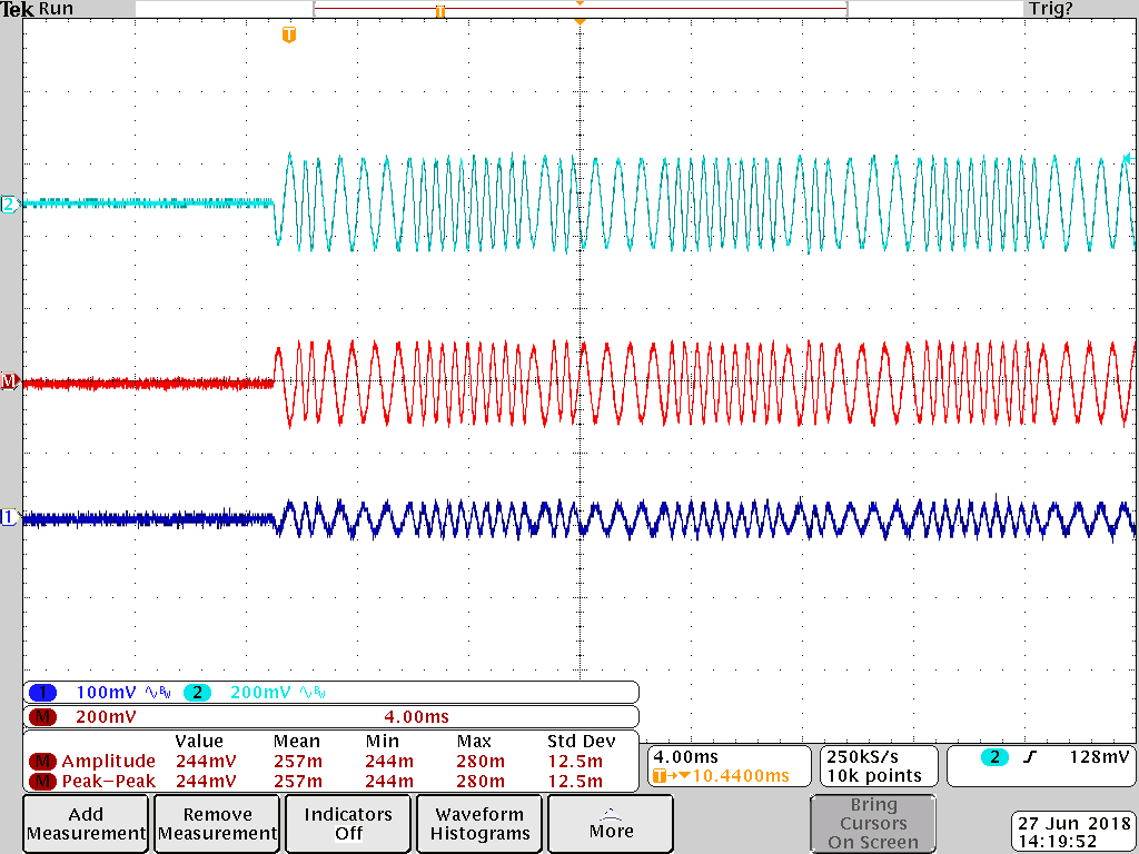
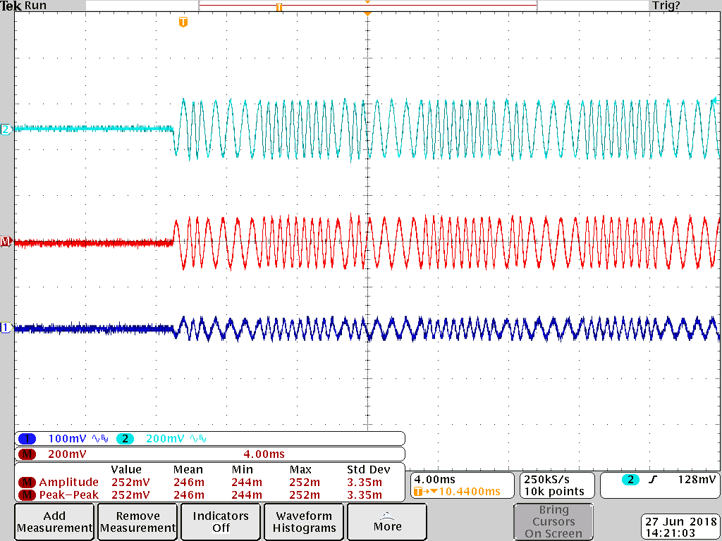
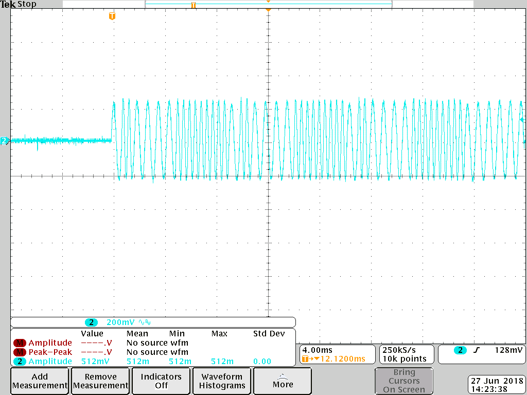
The question is the following: during different currents generation by DAC, during HART transferring there is different Hart signal voltage level on load resistance. If current is  12 mA the Hart signal level is 300 mV. If current is  4 mA than Hart signal voltage is 200 mV. When voltage level is  200 mV the Metran modem starts to receive error packets. On DAC8740 output pin (pin 14 , MOD_OUT) the signal level is 500 mV if current is  4 mA.

Why the HART signal level changes when the current changes?

If they reduce board current consumption down to  1,6 mA (lower STM's frequency) the situation becomes stable, the HART transfer is stable and the HART signal levels stay stable during different currents generated by DAC.

But they can't work on such low STM's frequency (no much time to do all operations)

How could they solve this problem on higher working frequencies?

Best regards, Anastasia

  • Hi Anastasia,

    In the higher current case (2.8mA) what is the amplitude of the HART signal above 12mV? Does the attenuation 'level off' like it is only happening it 4mA or is it continuous.

    For the higher current case (2.8mA supply, 4mA loop) can you provide waveforms of MODOUT on DAC874xH, C2 on DAC161S997, C3 of DAC161S997, and LOOP-? This will help show where this signal attenuation is occurring.

    Also, what happens if they reduce the current to a value between 2.8mA and 1.6mA? Does the signal become stable?

    Did they see this problem using just the EVMs with the EVM GUIs running on separate computers, the setup I described previously?

    Thanks,
    Garrett
  • Hello, Garrett!

    Thank you for a fast reply! I'll start with your last question.

    The problem described above takes place on their own board. All connections are done with your previous recommendations.. So I'll ask them to send me wafeforms and forward it to you.

    BEst regards, Anastasia

  • Hello, Garrett!

    I attach waveforms.

    Those pictures named as  "4 mA" and "5 mA" mean that it is a current assigned in current loop.

    With 12 mA and with 5 mA the Hart signal amplitudes are the same. That's why they made waveforms only with  5 mA.

    But here the current consumption is nearly  2 mA. 

    Do you need an extra waveforms? Can you download a .zip file?

    Best regards, Anastasiadac_osc2.zip

  • Hi Anastasia,

    I looked at your waveforms and in both the "4mA" and "5mA" cases the MODOUT waveform looks like it is unstable. It should be consistent amplitude but in the captures you provided it seems to shift downward. Also, the loop current HART signal looks very noisy and inconsistent which may be due to the issue with MODOUT. When I connected the EVMs I was able to get a clean HART signal onto the loop as you can see in my previous post. Did they switch R11 out for a 500 ohm resistor and switch the capacitors as I described?

    I also noticed they appear to be using a different board than the orderable EVM based on the picture in your previous post. Is this correct? This looks like a pre-release version and I don't have the schematic on hand. The schematic and the jumper settings in the EVM User's Guide will not be correct for this board. I would recommend they use the final version of the EVM which I have linked to below.

    http://www.ti.com/tool/DAC8742HEVM

    Thanks,

    Garrett

  • Hello, Garrett!

    We've ordered exactly DAC8742HEVM for customer. But on their own board they use XDAC8740HRGET ICs (also ordered as samples).

    I'll detail information about resistance and capacitance.

    Best regards, Anastasia

  • Garrett,

    They've made all changes according to your recommendations ( R11 changed to 499 Ohm, high capacitances on current loop input are put away, input DAC capacitances are swapped (С1 pin 14 and С3 pin 12).

    Maybe, smth wrong?

    Best regards, Anastasia
  • Hi Anastasia,

    Understood, I was just checking because the board photo in your previous post is definitely not the final version of the DAC8742H EVM.

    I wanted to ensure that the HART output amplitude does not change when the DC current is at 4mA compared to higher values. I set these boards up as I described in my previous post and took scope captures of the output and the HART input signal from DAC8742H. I confirmed that with how I have connected these two EVMs the output HART amplitude does not change with DAC161S997 DC current value.

    The first capture is with the loop current set to 10mA. The HART signal is the red waveform measured across a ~250ohm resistor.

    The second waveform is with the same HART signal input but the loop current set to 4mA. You can see that the amplitude is around 250mV in both cases.

    The third waveform is the HART input signal from DAC8742H measured at MODOUT while connected to DAC161S997 EVM (500mV pk-pk).

    You can also see that the HART input signal and the loop HART signal are clean waveforms. Even if the loop HART signal has an issue I would expect that the waveform would be fine on MODOUT. In the scope captures you shared the MODOUT signal was not what I would expect and the loop HART signal did not have a constant amplitude in ether the '4mA' case or '5mA' case. There is an issue with the MODOUT signal. Can they provide a capture of MODOUT when disconnected from DAC161S997?

    Thanks,

    Garrett

  • Hi Anastasia,

    Do you have any update on this thread?

    Thanks,
    Garrett
  • Hello, Garrett!

    One of customer's engineer was on vacation last week. So I'm waiting an update and I'll write to you ASAP :)

    Best regards, Anastasia

  • Garrett, hello,

    So..

    I attach customer's schematic (the striked out components are not mounted on board).

    Earlier they've done a mistake, the capacitors  (pin.С1, pin.С2 of DAC) were already mounted on their board according to TI's recommendations. With such configuration the HART signal in current loop was absent.

    They've done some modification (0.39uF to  С1 of DAC, 1000 pF on pin С3 of DAC). And the HART signal in current loop appeared (the waveforms were sent earlier).


    So does it mean that the capacitors on  DAC161S997 EVM are connected to DAC's pins right?
    I attach also waveforms from modem output (Hart out) with DAC disconnected (waveform №2,3 are scoped in  AC and DC modes).

    The schematic of this board (from which waveforms are scoped) is also in attachment.

    The waveforms are the same with DAC connected. The waveforms are scoped with loop current 12 mA.

    We could see on the waveform 1 the following: the board receives Hart frame from external modem (Metran), the frame is right. Then the board should send a reply. The reply frame is created but we could see only single burst (impulse).

    On customer's schematic the  С31 is  0,33 uF (they tried to increase it to  0,39uF, but the waveforms are the same).

    hart_osc.zip

    Best regards, Anastasiaivd_4_pcb_stm_v2_.pdf

  • Hi Anastasia,

    The correct capacitor values for these pins are C1 = 390nF, C2 = 220nF, C3 = 1nF. On the DAC161S997 C1 and C3 are swapped in layout only as I explained in my previous post. The schematic shown in the EVM is correct.

    When I performed this test with the two EVMs MOD_OUT has and additional 2.2uF in series before connecting to the DAC161S997 EVM.

    Here are a few things I would try:

    - The MODOUT pin requires a parallel capacitance of 5-22nF for stability as described in the datasheet. I would suggest adding this.

    - C22 is still a large value to be connected across the loop. I would suggest removing this as long as it doesn't cause a stability issue.

    - For testing, I would remove L2 and L3, these are huge inductors that could affect the HART signal.

    The capture of the loop current signal looks quite noisy and the HART signal does not look clean. It is also strange how the MODOUT signal is not consistent and has that transient behavior.

    Thanks,

    Garrett

  • hi, Garrett!

    Thanks a lot for your invaluable help. So waiting for results of your experiment.

    Best regards, Anastasia

  • Hello, Garrett.

    We need to clarify some moments. Earlier you suggested to make some modifications with  DAC161S997 EVM (maybe we undersood smth wrong):

    1. To swap around capasitors C20 and C17 (you said that there is an error in PCB layout - in place where these capacitors are switching). Also you said this fact heavily attenuates HART signal before gain stage. That's why we can't see no HART signal on output.

    There are  С1 = 390 nF and С3 = 1 nF on EVM. And if we swap them one to each other we'll get a scheme from my customer.

    But now you say that the schematic of EVM is right ? So should we swap them or not (or meybe we understand smth wrong)?

    They'll try to take away С22, L2 and L3 and look at waveforms.

    Best regards, Anastasia.

  • Hi Anastasia,

    To clarify, the schematic diagram in the EVM user's guide is correct but essentially the capacitors are installed in the wrong place on the board. So if they are actually using the EVM these will need to be swapped. If they are building a new board then following the schematic in the EVM user's guide is the same as the recommendation on the datasheet.

    Thanks,

    Garrett

  • Hello, Garrett! Now I understand. Thank's a lot. Do you already have some results from previous post?

    Best regards, Anastasia

  • Hi Anastasia,

    I was suggesting that they try these modifications to their board. In my previous tests, I used the EVMs for both devices but they have developed their own PCB. Did they ever get the correct waveforms using the two EVMs and the instructions I provided?

    Thanks,
    Garrett
  • Hi, Garrett.

    I'm clearing it up...because all last communication with them was about their own board.

    I'll write you as soon as I know it :)

    Best regards, Anastasia

  • Hi Anastasia,

    Do you have any update on this thread?

    Thanks,
    Garrett
  • HEllo, Garrett.

    Unfortunately I was on vacation for a few days. I'll try to refresh the information about our thread. Please don't close it.

    Best regards, Anastasia

  • Hi Anastasia,

    When do you expect to have more test results?

    Thanks,
    Garrett
  • Hello Anastasia,

    Do you have any news for Garrett on this topic?
  • Hello, Duke.

    Unfortunately, the customer's keeping silent...

    I suppose you could close this thread....I'm sorry about annoying you. I think they've solved problem.

    Thank you for great help. If smth goes wrong I'll write to forum again.

    Best regards, Anastasia

  • Hi Anastasia,

    I will go ahead and close this thread but we are happy to provide support. If they have any other issues please use the ask a related question button to start a new thread.

    Thanks,
    Garrett
  • Hi, Garrett!

    Thank's a lot for your help.

    Have a nice day)

    Best regards, Anastasia