This thread has been locked.

If you have a related question, please click the "Ask a related question" button in the top right corner. The newly created question will be automatically linked to this question.

ADS127L01: 2nd Harmonic Distortion Issue

Part Number: ADS127L01
Other Parts Discussed in Thread: , THS4551, THS4541, THS4520

Hi,

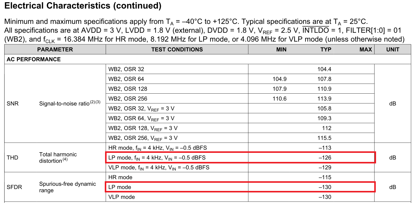
I got a feedback from our customer that 2nd harmonic distortion is higher than one which is mentioned in the data sheet by verifying ADS127L01EVM, so it is approximately -110dB when inputting 1kHz sine wave.
In addition, it doesn't change even if changing the operation mode(the high-resolution/low-power/very-low power modes) and VREF.
Could you please tell me how to improve this issue ?

Best regards,
Kato

  • Hello Kato-san,

    Thank you for supporting the ADS127L01.

    Harmonic distortion can be introduced through several aspects of the signal chain, including the signal source itself. Can you please provide details about:

    1. The signal source. What is the THD spec?
    2. The input signal chain. What components are installed?
    3. The signal configuration. Is it differential, pseudo-differential, or single-ended?
    4. The ADS127L01 schematic. Please show all relevant circuitry that connects to the ADC.

    Best Regards,

  • Hi Ryan-san,

    Thank you for your quick response.

    Please see the following comments.
    Would you double-check the 2nd harmonic distortion while changing the input signal amplitude by using ADS127L01EVM ?

    Q1. & Q2.
    There is no problem since the same measuring equipment is used for other competitor parts.

    Q3.
    It is probably the differential input.

    Q4.
    ADS127L01EVM is only used, so the external components aren't change.

    Best regards,
    Kato

  • Hello Kato-san,

    What is the input signal amplitude and frequency? How are they connecting the signal source to the EVM? Please confirm whether the source is connected differentially (J7 and J9) or single-ended (J9 only, J7 shorted to ground).

    Also, please provide the configuration settings for the ADS127L01:

    • HR, LP, or VLP Mode?
    • CLK frequency (JP6 setting)
    • Hardware Mode pin settings (OSR, FILTER, REXT, /INTLDO, etc.)

    Finally, can you confirm which revision of the ADS127L01EVM the customer is using? The latest revision is Rev. B.

    Best Regards,

  • Hi Ryan-san,

    Thank you for your reply.

    I will look into this and get back to you.

    Best regards,
    Kato

  • Hi Ryan-san,

    Could you please see the following information and double-check the 2nd harmonic distortion using ADS127LS01EVM ?

    <Evalutation Condition>
    - EVM Revision      : REV B
    - Input Signal      : 1.4Vpp @ 1kHz Differential(Signal Source : Audio Precision)
    - Operation Mode    : Low-power Mode
    - Oversampling Rate : 32/64/128/256 (* The same result can be obtained even if the setting is changed.)
    - Filter            : Wideband 2 Filter
    - CLK Frequency     : 8MHz
    - INTLDO            : Internal LDO Enabled
    - DVDD Voltage      : 1.8V/3.3V (* The same result can be obtained even if the setting is changed.)
    - REXT              : 60.4kΩ

    The 2nd harmonic distortion decreases if changing the input signal amplitude more than 2Vpp or less than 1Vpp.

    Best regards,
    Kato

  • Hello Kato-san,

    Thank you for providing the details. I will take some measurements on Monday to see if I can reproduce the issue.

    Can you please provide the raw data from the customer's setup for comparison?

    Beset Regards,

  • Hi Ryan-san,

    Thank you for your continuous support.

    I will confirm whether our customer can provide the raw data and get back to you.

    Best regards,
    Kato

  • Hello Kato-san,

    Please find the results below. Measurements were taken using an Audio Precision (SYS-2722) configured for "Balance Ground" output, 1.4 Vpp and 4.72 Vpp. Please note that the datasheet specs are tested and calculated with respect to a full-scale input signal, meaning the peak amplitude is equal to the reference voltage minus 0.5 dB (i.e. 2.36 Vp for VREF = 2.5 V).

    • CLK = 8 MHz
    • OSR = 256
    • HR pin = 1
    • /INTLDO = 0
    • Filter = WB2
    • 16,384 points

    VIN = 1.4 Vpp:

    VIN = 4.72 Vpp:

    Best Regards,

  • Hi Ryan-san,

    Thank you for your strong support.

    I will inform your test result to our customer and will ask him to double-check that.
    By the way, could you please approve my request as I would like to contact you via a private message on e2e ?

    Best regards,
    Kato

  • Hi Ryan-san,

    I just got our customer's test data on the same condition which you have already tested, then please accept my friendship, so I can privately send that to you.
    He is concerned not only the 2nd harmonic distortion, but also THD, so is my understanding correct that the THD performance improves if setting the LP mode, not the HR mode ?
    If No, could you please tell me that reason in detail since he would expect that the THD performance is less that -120dB if setting the LP mode ?
    In addition, is the THD performance improved greatly if replacing THS4551 with THS4541 ?

    Best regards,
    Kato

  • Hi Kato-san,

    I have accepted your friend request.

    Yes, you are correct about the improvement in distortion performance as you change from HR Mode to LP Mode. The reason for this improvement is the input voltage transients produced during sampling have more time to settle. The slower the CLK frequency, the longer the modulator sampling phase (approximately 1/2 the modulator period). With my same EVM setup, I only expect about 110 dB to 115 dB in THD performance at full-scale in HR Mode.

    One of the reasons for the better THD specs in the datasheet is that our characterization team used the THS4520, which is the predecessor to the THS4541. The higher GBW certainly helps the input voltage transients to settle faster. This will improve the linearity of the system and provide better THD results. However, the THS4541 consumes about 7.4x the power that the THS4551 consumes. Therefore, we used the THS4551 on the EVM to show a solution which was comparable to the ADC in terms of both performance and power.

    Best Regards,

  • Hi Ryan-san,

    Thank you for the information.

    I just sent the raw data via a private message to you, please check it.

    Best regards,
    Kato

  • Hi Ryan-san,

    Today, I visited our customer and discussed the THD performance for ADS127L01 with him, so got the following additional questions.
    Could you please give me your advice ?

    Q1.
    For your measurement result, did you use ADS127L01EVM which THS4551 is mounted ?

    Q2.
    For customer's raw data, could you please advise whether the measurement results for THS4551 are reasonable ?

    Q3.
    For the THD performance and the noise performance, are the most suitable high speed OpAmps THS4541 and THS4520 ?
    Please let me know if there are other solutions.

    Q4.
    Could you please share the schematics and the measurement results(the raw data & the FFT data) when using THS4520 and THS4541 ?
    * the schematics are included the information on the power supply circuit.

    Best regards,
    Kato

  • Hi Kato-san,

    1. Yes, I was using the ADS127L01EVM, which has the THS4551 mounted on the board.
    2. I will check the raw data from the customer today.
    3. For best performance, I would recommend using the THS4541 to drive the ADS127L01, especially for > 8 MHz operation.
    4. The measurement results taken with THS4520 can be seen in Figure 10 and Figure 11 in the ADS127L01 datasheet. These FFT plots were taken with an 8.192 MHz CLK and OSR = 32.

    Best Regards,

  • Hi Kato-san,

    I have reviewed the data that your customer shared. It does look a little worse than what I was able to measure on my bench with the same EVM.

    After reviewing the APx555 user manual, the APx555 should be able to source a sine wave with the same or better signal integrity than the AP2700, which I am using. A couple potential differences we should discuss are:

    1. Output Configuration: On the AP2700, there are two options for balanced output signals ("balanced grounded" and "balanced floating"). Please see the image below. Sometimes, I find that one setting works significantly better than the other. The difference lies in pin 1 of the XLR connector, which may be set internally to the AP chassis ground, or it may be left floating and tied to the ground of your local PCB (i.e. the ADS127L01EVM). Does the customer have the option to change this setting?
    2. Source Impedance: What is the source impedance setting that the customer is using? I am using 40 ohms, which is the minimum setting.

    AP2700 Output Configurations:

    The data from your customer does not look terrible, but I believe the prominence of the even harmonics may indicate a potential grounding contention between the AP and the EVM.

    Best Regards,

  • Hi Ryan-san,

    Thank you for the information.

    The information will be very helpful for me, so I will inform them to our customer.

    By the way, could you please provide the schematic for the FFT plot data which is taken with THS4520 if possible ?

    Best regards,
    Kato

  • Hello Kato-san,

    Please see attached (note that the ADC previously used a different part number):

    ADS1671_EVM_RevA1.pdf

    Best Regards,

  • Hi Ryan-san,

    Thank you for the information.

    I understood and will inform the information to our customer.

    Best regards,
    Kato

  • Hi Ryan-san,

    The THD performance is improved if replacing THS4551 with THS4541, but the 1/f low frequency noise increases slightly.
    So, could you please tell me the value for each resistor if setting the 0dB gain with THS4520 about the following schematic ?
    Unfortunately, there isn't the difference between two options for balanced output signals.

    Best regards,
    Kato

  • Hi Kato-san,

    Most of the circuit diagrams in the THS4541 datasheet use resistor values between 402 ohms and 499 ohms. For our testing with THS4541 on the ADS127L01EVM, we used 499 as the feedback and gain setting resistors. For the THS4520, Table 1 and Table 4 show recommended resistor values for various gain settings. It appears that 499 is an acceptable value for unity gain as well.

    Comparing the noise performance from the device datasheets, I do see that the 1/f noise is much better in the THS4520 than the THS4541:

    THS4520:


    THS4541:


    Best Regards,

  • Hi Ryan-san,

    Thank you for the information.

    Could you please confirm just in case whether my understanding is correct about the following schematic if applying THS4520 as the ADC driver ?
    I am concerned about whether THD4520 will work stably since it is different with the schematic which is mentioned in THS4520 data sheet.

    Best regards,
    Kato

  • Hello Kato-san,

    I'm not completely certain if the circuit you are describing is optimized for stable unity-gain operation. Those four resistors you outlined will be reduced to 499 ohms, like you said. However, I don't know if the THS4520 is stable with only resistive feedback to drive the R-C input filter for the ADC. The FDA may require some compensation components as well, as shown in our characterization board schematic.

    Another suggestion would be to verify this circuit with the high-speed amplifier experts in the High-Speed Amplifiers Forum.

    Best Regards,

  • Hi Ryan-san,

    Thank you for the suggestion.

    I understood and have already posted as below.

    THS4520: Configuration for 0dB Gain
    https://e2e.ti.com/support/amplifiers/high_speed_amplifiers/f/10/t/707619

    Best regards,
    Kato