This thread has been locked.

If you have a related question, please click the "Ask a related question" button in the top right corner. The newly created question will be automatically linked to this question.

LDC1101: LDC1101 / Output data is not changed thogh target distance is changed

Part Number: LDC1101


Hi,

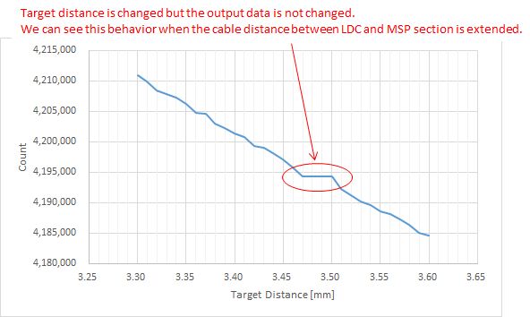
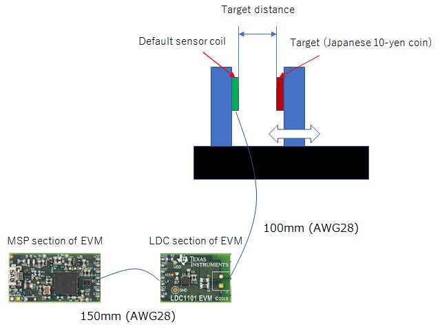
Now the customer evaluates LDC1101 EVM and they found the strange behavior that the output data is not changed thouth target distance is changed as attached graph. And this behavior can be seen only when we separate the LDC section with MSP section and use long cable. We can't see it with short cable or LDC and MSP section is connected.

I'd like to ask you why such behavior is happened when we use long cable between LDC and MSP section.

[Setting]

  • LHR mode
  • VDD = 1.8V
  • CLK frequency = 12MHz
  • Rcount = 0x37
  • All components including sensor coil are default

Best Regards,

Satoshi / Japan Disty

  • Hi Satoshi-san,

    I believe you are experiencing a phenomenon called resonance locking, which you can read more about in section 2.5.3 of this app note. This is a parasitic effect that occurs when the EMI frequency is an integer multiple of the resonant frequency of the LC tank.

    Could you share the raw code value at the flat spot on the graph? You can find the exact value of the data register in the Configuration tab of the GUI, or in the Registers tab. This would help us confirm that the 40MHz reference clock is causing a resonance locking issue.

    If resonance locking is your issue, this can be resolved in a few ways. You may need to use a series termination and a twisted pair made of your reference clock and ground to mitigate this. You can also adjust the values of L and C in your LC tank to move the frequency away from common fractional ratios of the reference clock.

    Regards,

  • Hi Jones,

    I appreciate for your response. Here is the output log data at LHR mode. Is this the data you requested?

    It will be appreciated if you can give any comment for this data.

    Target Distance
    [mm]
    Output data
    3.30 4211015.968750
    3.31 4209961.437500
    3.32 4208458.125000
    3.33 4207854.125000
    3.34 4207326.375000
    3.35 4206198.906250
    3.36 4204844.000000
    3.37 4204689.125000
    3.38 4203036.625000
    3.39 4202283.531250
    3.40 4201455.625000
    3.41 4200851.937500
    3.42 4199351.656250
    3.43 4199049.906250
    3.44 4198225.781250
    3.45 4197092.875000
    3.46 4195813.562500
    3.47 4194304.000000
    3.48 4194304.000000
    3.49 4194304.000000
    3.50 4194304.000000
    3.51 4192336.781250
    3.52 4191278.750000
    3.53 4190221.312500
    3.54 4189692.718750
    3.55 4188635.843750
    3.56 4188107.562500
    3.57 4187201.875000
    3.58 4186373.000000
    3.59 4185091.250000
    3.60 4184563.718750

    Best Regards,

    Satoshi / Japan Disty

  • Hi Satoshi-san,

    The data you sent is very helpful. The flat spot you are seeing is when the sensor frequency is exactly 1/4 of the reference clock, which supports our resonance locking theory. I believe that the longer cable is acting as an antenna and EMI is producing the resonance locking issue. 

    In addition to the suggestions I mentioned above, the customer should try using shielded cables and shielding the LC tank as much as possible. They should also change the capacitor so that the LC tank frequency does not approach the 1/4 ratio with the reference clock. It's important to avoid this frequency during the full movement range of the target. This is fairly easy to calculate using the Inductive Sensing Calculator Tool.

    Regards,