
- Ask a related questionWhat is a related question?A related question is a question created from another question. When the related question is created, it will be automatically linked to the original question.
Hello.
I find a mistake in the schematic for TIPD158 "Low-Cost Loop-Powered 4-20mA Transmitter, EMC/EMI Tested".
On page 25, Figure A-1 "Electrical Schematic", Appendix A, the Vreg should be 3V, not 5V (I assembled this circuit and measured).
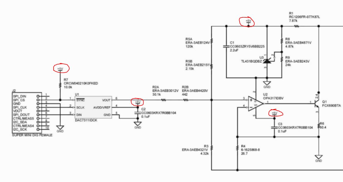 Even on page 9, there is a comment "The loop regulator uses the TL431B programmable shunt regulator to provide a 3 V supply to the loop transmitter using the rectified supply voltage from the diode bridge. Figure 8 shows the loop regulator section of the design."
Kind Regards,
Pawel Szczurowski


