This thread has been locked.

If you have a related question, please click the "Ask a related question" button in the top right corner. The newly created question will be automatically linked to this question.

ADS1298: Bad signal quality

Part Number: ADS1298

Dear all,

I have a problem with the signal quality while using ADS1298.

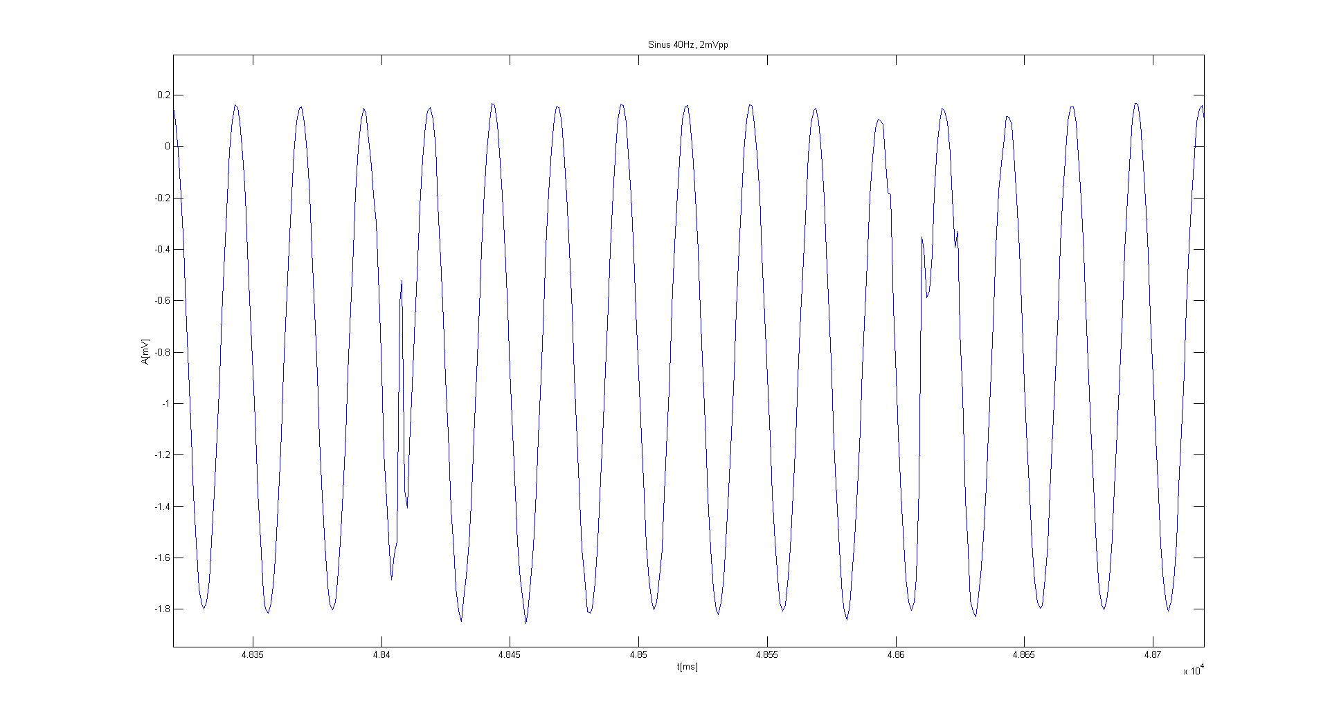
I applied a sinusoidal signal (2mVpp and 10Hz, generated by a waveform generator) to the ADS1298 inputs.

The output doesn't look good. The amplitude and the frequency are as they should. The shape of the signals are bad, and it varies from channel to channel. The same result can be noticed with different amplitudes and different frequencies. The sampling rate is 1kSPS.

The Vrefp is 2.4V (meansured by a multimeter).

The signals below are the raw signals from ADS1298 (no post-processing ect).

Does anyone face similar problem?

  • Hello Jack,

    Thanks for your post!

    Are you feeding this signal through an anti-aliasing filter before it reaches the input pins of the device? If so, what is the cutoff frequency?

    For the digital filter, are you using high resolution mode or low power? Are you allowing sufficient time for the digital filter to settle before applying the sine wave to the inputs?
  • Hello Alexander,

    thank you for your answer.

    No, I have no anty-aliasing filter before inputs (only resistors).

    If you ask about Config1, I use high resolution mode.

    The chart shows the raw signals from ADS1298 (no analogue/ digital filters , ect). Only filters which are used here are these internal in ADS1298.

    The signal doesn't get better even if the recording last long (like 5mins).

    Best regards,
    Jack
  • Hi Jack,

    Happy to help!

    I strongly recommend adding a capacitor (either single ended or differential, depending on your input configuration) to create an anti-aliasing filter. This should remove the high frequency signals that are aliasing back into your measurement spectrum.
  • Hi Alexander,

    I don't believe that it is an anti-alisaing filter as I wrote, I have the right amplitude and frequency.
    Especially, when my signal is 10Hz and sampling 1kHz (information in the first post)
  • Hi Jack,

    This looks like high frequency distortion. Your input signal is the dominate signal being processed by the ADC which explains why the amplitude and dominant frequency look correct, but additional high frequency signals are being added to the fundamental.

    Adding an appropriately designed anti-aliasing filter (RC) to the inputs of the ADS1298 should remove the high frequency distortion and improve the signal quality.

    This TI Precision Labs video may be helpful for you:
    training.ti.com/ti-precision-labs-adcs-aliasing-and-anti-aliasing-filters
  • Hi Alexander,

    thx for you explenation. Now, I understand what you meant.

    For sure after filtering  (low, high, notch filter) the signal looks better. I don't deny it.

    But there is an other problem.

    Look, this is a raw signal for 40Hz (amp should be 2mVpp).

    This is the same signal only filterd (low pass 450Hz, highpass 20Hz, notch 50Hz+harmonics) I am concern about the shape of the signals:

    How to explain the bizzare shape of the signal after filtering?

  • Hi Jack,

    I'm glad to see that the filter improved your result.

    This looks like the device is overwriting samples before they are fully transferred from the device.

    What is the frequency of your SCLK? Is SPI able to keep up with the data rate and the number of bits to read for each sample?
  • Hi Alexander,

    The spi clk is 8Mhz, sampling freq 1kHz.

    I was thinking about it too, as I get most of the time good data and sometimes corrupted. So it maybe a software issue.
    I have been investigating this posibility for last two days.

    Best,