This thread has been locked.

If you have a related question, please click the "Ask a related question" button in the top right corner. The newly created question will be automatically linked to this question.

FDC2112: Instable data register value

Part Number: FDC2112
Other Parts Discussed in Thread: FDC2114

For my application I used 3 FDC2112 to measure 5 sensors and one reference. The sensors are about 22pF PCB pads with no additional chip capacitors. The reference is just a PCB trace with no significant capacitance at the moment. The inductor used is 18uH. They share one I2C bus and are selected using the SD pin. To initiate a measurement the SD pin of a device is asserted and after 4 ms wakeup time the device is configured. The status register is polled until the conversion result for channel 0 and 1 are available. Then the data registers are read (one 16 bit word from 0x00 and 0x02, not reading the LSB.) Then the SD line is deasserted and the process is repeated for all 3 devices.

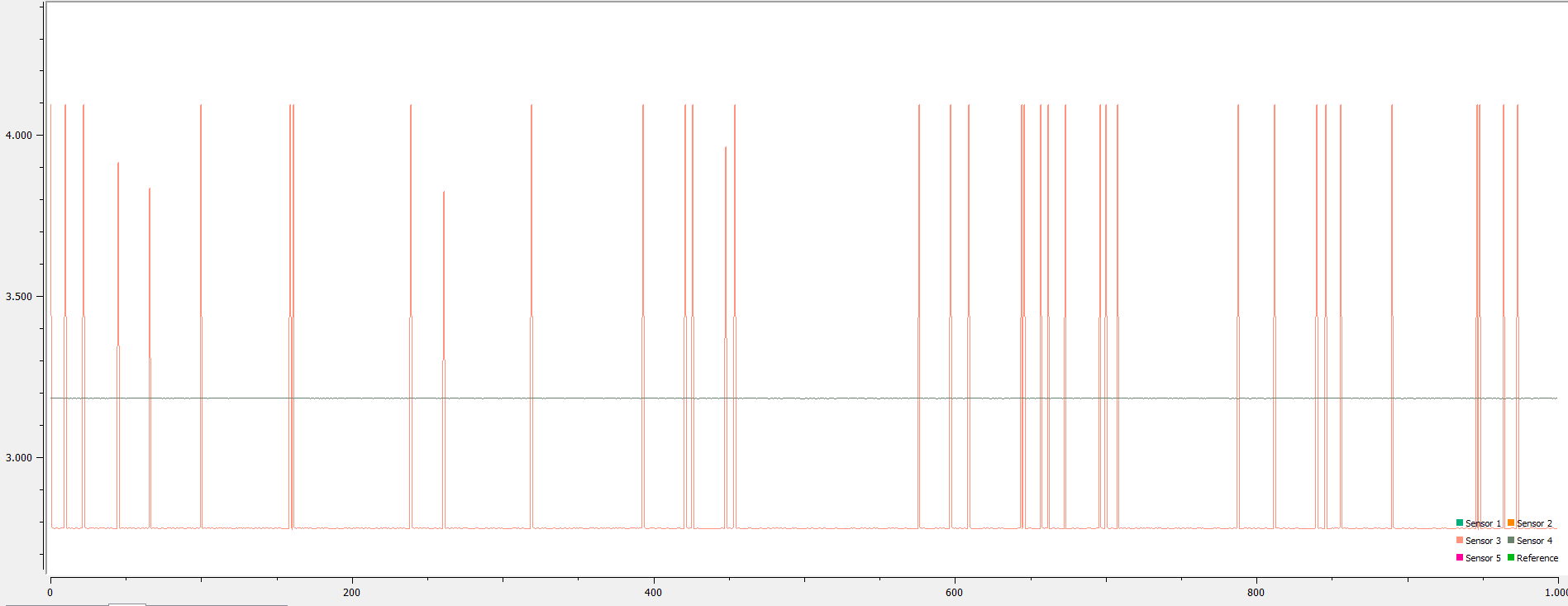
Upon inspecting the data register values it shows large spikes at irregular intervals.

  1. Increasing the capacitance by placing a glass container filled with tap water on a sensor increases the amount of spikes significantly.
  2. We see that these spikes are influenced by the voltage ripple on the power supply. Changing out our switchmode power supply for a linear one reduces the amount of spikes, but does not completely eliminate it.
  3. Reducing the conversion time to the minimum required eliminates the spikes.
  4. Increasing the conversion time to twice the minimum required re-introduces the spikes.
  5. Reducing the status register polling interval from 4ms to 1ms eliminates the spikes. (with the conversion time set to twice the minimum.)

  • Hi Koen,

    I think the first question here is if these spikes are actual data recorded by the FDC devices or if the data is being corrupted on the I2C lines, or a combination of both. Because physical changes to the sensor and changes to the conversion time affect the frequency of the spikes, I am inclined to believe that the spikes are real data from the FDC. I have a few questions to help debug in this vein:

    First, what are the values of the spikes and the normal data readings? Are the spikes always the same magnitude or do they vary?

    Do you have any noisy signals routed close to your INAx and INBx traces? These traces are very sensitive, and the spikes could be caused by crosstalk. Although the devices themselves could be sensitive to power supply ripples, the INA and INB traces could also be affected if you have VDD routed to close to them. Even if you don't have any noisy signals near them, if the INA and INB traces are too long you could be experiencing EMI issues (though this seems least likely to me).

    Because changing the status register polling interval can eliminate the spikes, I would also recommend checking to make sure that you don't have any noisy traces that could corrupt the I2C data. This interval should not have an affect on the data stored in the FDC's registers, which is why I'd like to make sure you aren't also having an I2C issue.

    Regards,
  • Hi Kristin,

    The magnitude appears to depend on the conversion time and clockdividers.
    Spikes are not constant in magnitude as shown in the image below. This is with RCOUNT=0x0200 and CLOCK_DIVIDERS=0x1004

    To my knowledge there aren't any traces close to the converter's input. We performed a precompliance EMI test both radiated and conducted and we saw no change in the measurements.

    Edit: Two out of three devices have the I2C lines under the input traces, but they are separated by a groundplane and we see the spikes for all devices, not just the ones with I2C traces under them.

    Edit2: It seems like waiting ~10ms after configuring the device before reading the data register resolves this issue. I could not find this in the datasheet.

    Cheers,

  • Hi Koen,

    Did waiting 10ms after configuring the device completely resolve your issue? Or was it just a temporary fix?

    Regards,
  • I have ran the test for several minutes and it appears to have solved my issue. Could I also use the settlecount register for this settling delay?

  • Hi Koen,

    It's surprising to me that waiting before polling the data registers solved your issue, but you should be able to use the settlecount setting to achieve the same effect. However, increasing settlecount will decrease your overall sample rate. The FDC2114 shorts channels to ground when they are not being measured, and restarts their oscillations when they are being measured. Settlecount determines how long the device waits for stable oscillations before it begins measuring a channel's resonant frequency. An especially long settlecount will increase the time it takes to measure every sample. If sample rate is especially important to you I would suggest waiting just once after configuring the device.

    Regards,