This thread has been locked.

If you have a related question, please click the "Ask a related question" button in the top right corner. The newly created question will be automatically linked to this question.

LDC1612: Linear Displacement measurement using Inductive sensing.

Part Number: LDC1612

Hi,

We are looking for linear Displacement measurement sensor based on Inductive sensing technology.

Requirement is mentioned below.

1. Total traveled distance will be less than 100 um.

2. Resolution needed less than 1 um.

3. Maximum target diameter will be 20 mm.

4. Spacing between targets and coil is flexible.

Is it possible to measure such small displacemt of less than 100 um using Inductive sensing?

I read sub micron measurement is possible in LDC1612 datasheet.

Could you help me to understand the feasibility of this requirement using inductive sensing?

Thank you,

Regards,

Rajesh M

  • Hi Rajesh,

    It is possible to measure displacements of less than 100um using the LDC1612. However, the resolution of your system depends on many variables, including your sensor coil size, your target size and material, the noise floor of your system, the distance between your target and your sensor coil (both minimum and maximum), the required sample rate for your system, and whether you need to detect absolute distance or relative movement.

    If you are new to inductive sensing, I would recommend starting with these app notes:

    LDC Sensor Design

    LDC Target Design

    If you are already familiar with these app notes or know how to design inductive sensing coils and targets, I would suggest reading through this app note:

    Optimizing L Measurement Resolution for the LDC161x

    Finally, one of the best tools for determining the feasibility of your system is the LDC Tools Excel Calculator. The Spiral_Inductor_Designer and LDC131x-161x_Config sheets will be the most useful to you. All of the sheets in the calculator tool include .pdf instructions. You should be able to estimate your resolution with this tool. I would recommend starting off by designing a sensor coil with the Spiral Inductor Designer sheet, then importing these settings into the LDC131x-161x_Config sheet. Then use the Axial Target Movement Calculations section to calculate the frequency shift between your maximum target distance and 1 micron closer than that. Then compare this frequency shift to your expected noise floor to determine if your SNR is high enough to support sub micron resolution. I would also recommend using the LDC1612EVM to measure the noise floor of your system.

    Regards,

  • Hi Kristin,

    Thank you for the inputs, I am working on the suggested documents.

    But in this application we want to measure deflection of steel body because of load applied on its center.  There is one sheet of metal deflection in LDC Tools Excel Calculator and I can see the deflection graph on it.

    Sorry, but I am not able to visualize where they have placed Inductive sensor in rectangular button or circular button in that sheet.

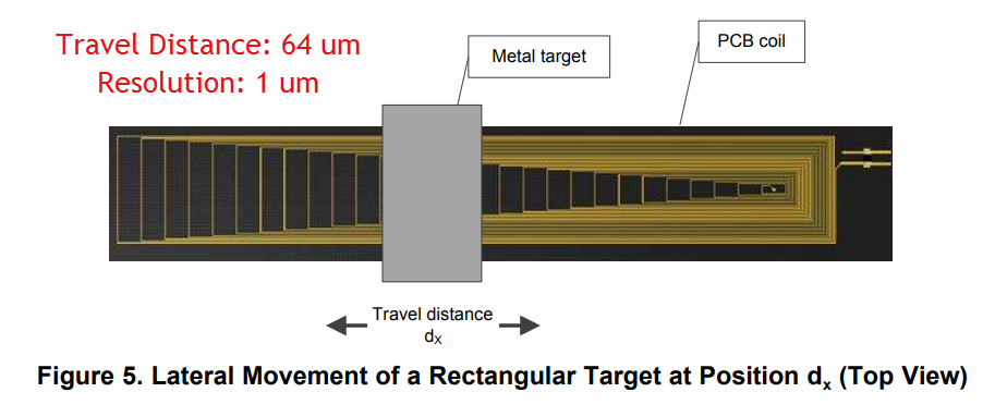
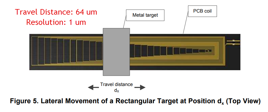
    Our application requirement don't allow axial moment, we need have to go for lateral displacement, most probably as shown in the attached document.

    Is this feasible with this arrangement?  

    Thank You,

    Regards,

    Rajesh M

  • Hi Rajesh,

    In the Metal_Deflection sheet, the sensor coils are placed directly underneath the rectangular and circular buttons. The Load Conditions figure shows a cross section of the system, where the top horizontal line is the metal and the bottom horizontal line is the sensor coil.

    I do not believe that this type of sensor would work for the travel distance you expect. This type of sensor coil is more suitable for larger travel distances. A travel distance as small as 64 microns is most doable with axial distance sensing, because the coil is most sensitive to axial target movements.

    Regards,
  • Hi Kristin,

    Thank for the inputs.

    As you said that this is doable with axial distance sensing, are you pointing towards configuration coil sensor shown in the attached file?

    Or,

    If you are talking about other options  then please suggest me any document or link. I will start working in that direction.

    Thank You,

    Regards,

    Rajesh M

  • Hi Rajesh,

    Figure 4 in LDC Sensor Design (link in my original reply) is the best diagram of axial sensing. The target and sensor system can be oriented in any way, as long as the target and the sensor remain in parallel planes and the target moves closer to and farther from the sensor.

    Regards,
  • Hi Kristin,

    Thank you for the support, it really helped me.

    Regards,

    Rajesh Matere