Because of the Thanksgiving holiday in the U.S., TI E2E™ design support forum responses may be delayed from November 25 through December 2. Thank you for your patience.

This thread has been locked.

If you have a related question, please click the "Ask a related question" button in the top right corner. The newly created question will be automatically linked to this question.

ADS1115: Low side battery current datalogger solution

Part Number: ADS1115
Other Parts Discussed in Thread: INA190, INA190EVM

Would like to interface some kind of "low side" lead-acid battery current monitor for off-grid solar homes to an ESP8266 datalogging microcontroller with built-in WiFi using I2C, preferably. 

Battery current for a typical 24V house can range from -100Amps (running toaster, -10mV shunt voltage) to +60Amps (during peak solar charging, +6mV shunt voltage). We are part of a 600 acre subdivision of off-grid homes and need to get this data online for detecting anomalies that could damage the expensive battery banks.

Almost every home has a 500A/50mV low side "deltec" current shunt. And we would like to be able to use that shunt for monitoring battery current. The problem is we want to be able to measure down to one amp and ideally down to 250mA, if economical.

We are currently using the ADS1115 in single-shot, differential mode and during calibration, it is clear that 16 bits with 16x gain is not enough resolution for current below 4Amps (400uV or less on the Deltec shunt) since the calibration factor starts to jump all over the place. This is because the ADC outuput value is 12  at 0.89Amps (89uV DC signal) as opposed to 6436 at 500 Amps (50mV DC signal). So it seems to be clear that we need to increase resolution maybe using oversampling and decimation or some kind of very low noise amplifier or maybe a 24bit ADC??

We want to power everything with a single 5V power supply. We are using the ADS1115 as well as the ESP8266 at 3.3V via a voltage regulator.

  • Zac,


    I think that a 16-bit ADC has plenty of resolution, but you're not using much of the full scale range. With an input signal that is only 0 to 50mV, and an ADC (when in full gain) that has a full scale range of ±256mV, you only use about a 1/10 of the codes to represent the value.

    While you could use a 24-bit ADC in gain, it may not be simple. Many of the the 24-bit ADCs have PGA front end that are capable of gains up to 128. However, the input range is limited because the PGA is implemented similar to an instrumentation amplifier. In high gain, the input signal must be near mid-supply. If you wanted to use this PGA/ADC combination, you may need to construct a bipolar ±2.5V supply for the analog ADC supply (the digital supply would remain unipolar).

    Instead, I would keep the 16-bit ADC and insert a gain stage to use more of the range of the ADC to increase your resolution. As an example, you could use the new INA190 in a gain of 25, setting the ADC to a larger scale. This would give a full range of 1.25V output, with a ADC range of ±2.048V, which would be about 20000 counts. Note that you could use other gains and other shunt resistance values to play with the resolution.

    I haven't run through any analysis of the offset and gain error, but the INA190 are moderately low in both. I'd check the noise and see if it works for your system. Regardless, there is an INA190 evaluation module, and this should be something you could insert into your system to test it.


    Joseph Wu
  • Thanks again, Joseph!!

    I think you nailed it!

    So let me see if I understand correctly: I should set the gain of the INA190 to 25 and set the gain of the ADS1115 to 1 and this will, for a -500Amp to +500Amp (-50mV to +50mV) signal, send a usable input voltage range of +0.4V (-500A, -50mV) to +2.9V (+500A, 50mV) to an ADS1115 running at 3.3V single sided supply using a 1.65V reference, if such a thing exists, correct?
  • Zac,

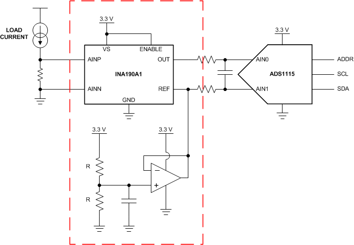
    That's correct. However, you really don't specifically need a 1.65V reference. You just need a stable midpoint. You should just be able to use a buffered voltage divider. It should be as simple as this:

    If you already use the ADS1115, all you need to do is insert the section in the dotted line. You'll also need to change your code, because right now, you use the smallest range of ±0.256 V and need to change that to the ±2.048 V range. You'll need to scale the current to the correct measurement. I'd also note that you can change your current sense resistor values smaller or larger and scale the ADS1115 range to get a better resolution. Regardless, this shouldn't take long to test if this works.

    Joseph Wu

  • Thank you for the schematic, Joseph! So the INA190 does not have a differential output?! But I see you are using the REF pin as "IN-" on the ADC. It makes sense! :-) Can't wait for the parts to arrive.

  • Zac,


    Thanks, I'd note that this circuit (with a buffered voltage divider for the REF pin) is already put together on the INA190EVM board. If you do get it, you'll still need to get an op-amp because it's not populated on the board. I think you may also need another 10kΩ resistor too.

    I wouldn't really say that the INA190 doesn't have a differential output. I'd say instead that the INA190 gives an output around a common point. For a single ended output, you generally a positive output with reference to ground. The INA190 gives a positive or negative output with reference to the REF pin.

    Good luck with this circuit. If you end up using it and need someone to review the schematic, post back and we can discuss it more.


    Joseph Wu