This thread has been locked.

If you have a related question, please click the "Ask a related question" button in the top right corner. The newly created question will be automatically linked to this question.

CCS/LMP90100: Bridge sensing and 2-wire RTD

Part Number: LMP90100
Other Parts Discussed in Thread: PGA900, ADS124S08

Tool/software: Code Composer Studio

Hello TI experts

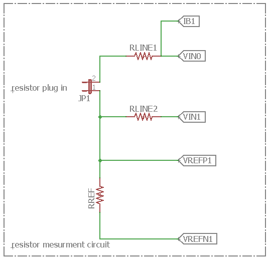
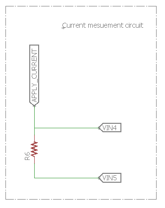
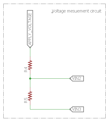
I want to use the LMP90100 in 2 different sensors at the same time but i will not be using the RTD and the load sells as components but instead i will be using for the bridge 3 fixed resistances and one that i will be changing manually as for the RTD i will be using a resistance that i will be changing as well. My goal is that i want to create a precision multimeter and for a start i want to mesure different resistances with 2 diffrent methodes to validate the results.

I tried doing that with the PGA900 but i had a problem withreading the ADC registers, and my question is is it possibol to do theise two different montages on the same LMP90100 and if so is there any recommandations or any side devices that i should use. if not, what AFE would you recommand to do the desired work

regards ! 

  • Maryem,


    I think there are many devices that could make the measurements you want. Another device that I think would fit your needs would be the ADS124S08.

    However, I'm not very clear on what it is that you want to measure. Can you please post back with a basic block diagram of the measurements that you want? I would want more of an explanation of the measurement and how you have your bridge set up.


    Joseph Wu
  • Maryem,


    I haven't heard from you for a while. Hopefully my comments helped or you've solved your problems with the LMP90100. I'll go ahead and close this post. If you continue to have problems with the LMP90100 or want to discuss other devices, post back and we can renew the discussion.


    Joseph Wu
  • hello Joeseph,

    sorry it took me so long to reply, here is my schematics to further explain what i want to do with the LMP90100. First, I'm not going to use an RTD as a componenet in order to mesure resistance, instead I'm going to use an acutal resistor and plug it into a jumper and mesure its value using the same principle. As fo mesuring voltage and current hope the schematics expalin what I want to do. My question now, will I need to amplify the signal ? will I need a protection circuit ?

    what will happen if I pass the limits of the LMP90100?

    hope you'd be able to answer soon

    regards     

  • Maryem,


    I'll comment on the circuits first and then we can discuss some of your other questions.

    For the first schematic, IB1 should be moved to the other side of RLINE1. You want the excitation current on the opposite side of these resistors (I assume they are used for input filtering with a differential capacitor). The way that you have it set up, the voltage from IB1*RLINE1 is added to the measurement seen between VIN0 and VIN1.

    Here, the measurement is ratiometric. The measurement is will be based on how large the test resistor is compared to the reference resistor and isn't measured against an exact voltage reference. RREF should be a precision resistor with high accuracy and low drift.  Any error in the reference resistor will be seen as a gain error.

    Also, VREFN1 should be connected to ground. The current needs to be sunk somewhere.

    For the second current measurement, R6 also needs someplace where the current can. You could tie VIN5 to ground, but there may be limitations on your input. If you use the buffer, or if the gain is between 16 and 128, then VINN cannot be at ground. However, you can use as much as a gain of 8 with that setup. The analog input range is covered in the Electrical Characteristics table on page 8.

    For the third voltage measurment, the same comments apply as the previous circuit. There needs to be a lower connection for the current to flow to (presumably ground) and you may be limited by the input range if you use the buffer or higher PGA gains.

    Returning to your questions, answers depend on you want out of your system. First you asked, if you needed to amplify your signal. That would depend on the level of performance you want. The resolution you get out of the device will depend on what the IB current, the reference resistance, data rate, maximum resistance for that you expect to measure, and the gain of the PGA. If you don't need a lot of resolution, then you may not need much gain. Look a the noise floor based on the settings and calculate what noise you have compared to the max measurement. This will determine the resolution of the system.

    The second question of will you need a protection circuit, also depends on what environment you expect to operate this system in? Do you expect ESD events? Do you expect sustained over-voltage events for the system. Without knowing what you expect for operating conditions, I'm not sure how to answer this question.

    Lastly, you asked what will happen if I pass the limits of the LMP90100?. I'm also unsure how to answer this. What exactly are you asking? The datasheet does give an absolute maximum ratings table on page 5. Beyond these limits, you risk damage to the device.

    Regardless, I'd need more information about what you want to measure and what specifications you want. There wasn't much in the schematics about your system. It would be better to show the full schematic, and have a description of what you want to measure, and what want for performance.


    Joseph Wu

  • Joseph,

    My desire with the LMP90100 is to create a precision multimeter basicly to mesure a resistor value or current or voltage values with very hight precision and display that value on LCD16*2 and eventually display some thing like the image below. I don't have a full schematics yet and the previous schmatics was just a draft to try to explain what i would like to acchieve

    Regards

  • Maryem,


    Have you been able to put together a schematic for review? I was curious to see if you have put together a circuit. I'll close this post for now, but if you have a schematic, you should be able to post it again. If you get locked out of this thread, you can just start a new one.


    Joseph Wu