This thread has been locked.

If you have a related question, please click the "Ask a related question" button in the top right corner. The newly created question will be automatically linked to this question.

ADS1299EEGFE-PDK: EMG input problems

Part Number: ADS1299EEGFE-PDK

Hi all

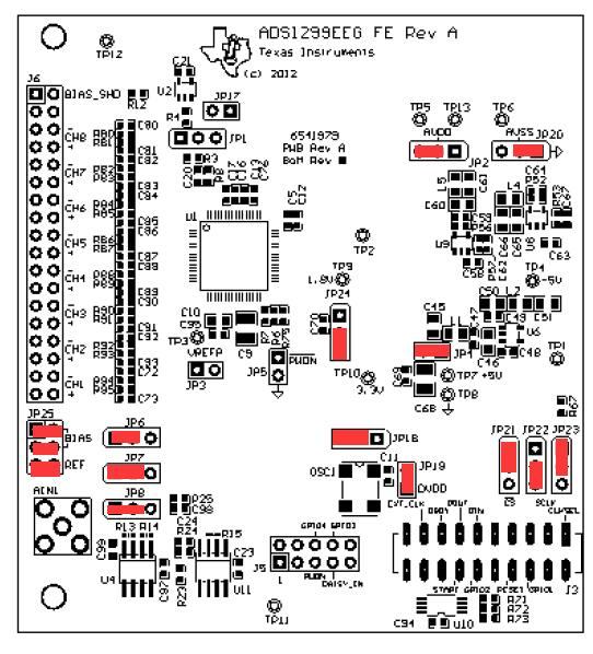
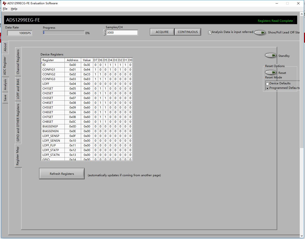
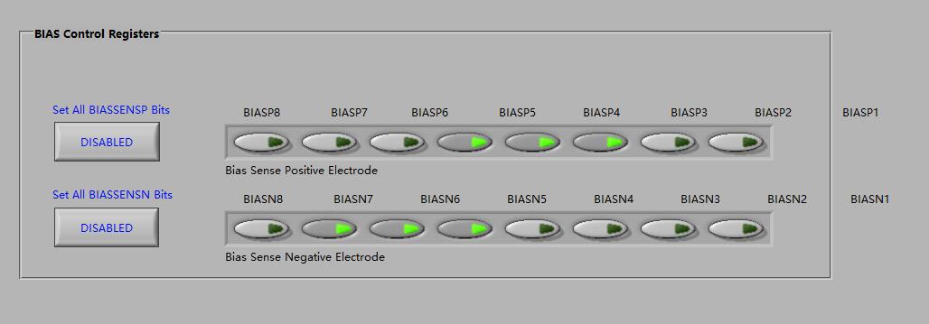
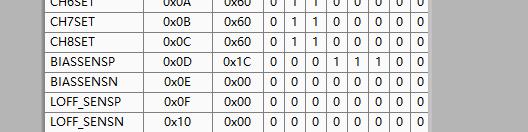
I got some problems when using ADS1299EEGFE-PDK to get some EMG data. I tried the single ended settings first as I'm going to use that in my future applications, but I failed. Then I tried to use the simplest differential input settings to try to get familiar to this board first, but I failed again. The signal I got was just 50Hz noise and I can't see the normal EMG signal in it. Here's my jumpers settings and register settings, can you guys give me some suggestions? 

  • Hello Liu,

    Thanks for your post and welcome to the forums!

    According to the diagram you posted, it looks like your jumper settings are unchanged from the default factory settings. Your register map looks fine as well.

    I would recommend resetting the board and confirming that your signal generator is outputting as expected with an oscilloscope.

    To reset the board: close the GUI, unplug the power to the MMB0, wait a moment, plug power back in, press and hold the reset button on the MMB0, open the GUI.

    You can also probe the decoupling capacitors around the device to confirm that the device is receiving the correct power rails. AVDD, AVSS, VCAP3 (AVDD +1.9V), and DVDD.
  • Hello Mr. Smith,

    Thanks for you advice! I've tried the suggestions you gave me and get the signal from a functional signal generator successfully. But I still have a question, when I comes to EMG signal, the noise of 50Hz become too large to accept, and I'm not sure that's the problem of my electrons or the problem of settings on the board. Can you give me some suggestions about this? Thank you again!

    Liu.

  • Hi Liu,

    Happy to help!

    This noise is from the power lines and/or lights in your work area. This is countered with the BIAS pins provided by the device. The BIAS pins will take a voltage (either mid supply, externally fed, or a average of the input channels of your choosing) and inject it onto the patient to counter the noise. When the signals are measured deferentially, this common mode noise is cancelled out leaving you with a clean signal!

    Take a look at section 9.3.2.4.5 for more information. This is a complicated topic so read everything thoroughly!
  • Hi Mr.Smith,

    Thanks for your help. I can finally get some reasonable data now. But I still have one question about the software. 

    This is an example, as I shown in the picture, I can't change the register value of BIASSENSN independently. I can only turn on all eight channels or turn off all of them, but I think it should be independent according to the chip manual. I want to know if it is a bug or it should be like that.

    Thank you again for your kindly and professional help!

    Liu Huaiyang

  • Hello Liu,

    Happy to help!

    I am able to toggle the individual BIASSENSN register's without issue. Resetting the boards may help.