This thread has been locked.

If you have a related question, please click the "Ask a related question" button in the top right corner. The newly created question will be automatically linked to this question.

LDC1101EVM: Difference between UserGuide Value and Measurement

Part Number: LDC1101EVM

Ladies and Gentlemen,

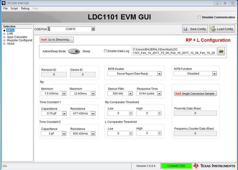
we use your LDC1101EVM and measured an Rp of about 4.2kOhm with the given PCB-coil and the TI-GUI. The "LDC1101EVM User Guide" shows on page 8 a table with RP@3 MHz (no target) 10.3 kΩ for the given Setup.

Is there something wrong with our measurement or is the shown value in the user guide wrong.

Your help is much appreciated.

Thanks.

  • Hi Frank,

    Could you share the settings you’ve configured in the GUI? I believe the value specified in the user’s guide was measured in the lab with a network analyzer, so it should be very accurate.

    Regards,
  • Hi Kristin, hello TI-Support,

    attached you can find pictures showing the Setup used with the GUI.

    First three pictures show the settings and the corresponding Rp and Proximity results offered by the GUI.

    If we change the RpMIN setting to 0.75kOhm no Rp is shown by the GUI only Proximity readings are shown - can you please explain that behaviour, too?

    Meanwhile we measured the Rp as described in chapter 4 of your document "SNOA936–October 2015-Measuring R p of an L-C Sensor for Inductive Sensing" and received a value of 4.9 kOhm.

    Thanks,

    Frank.

  • Hi Frank,

    I've been experimenting with an LDC1101EVM and the GUI, and my results more closely match yours than the specified value in the user's guide. The Rp for my EVM is about 5.48 kOhms. Temperature and other environmental factors could account for the differences between our readings, but not for the large difference from the value in user's guide. I will investigate to see if we modified the coil after the user's guide was written and need to update the specified values.

    I'm also not sure why changing the Rp min value to 0.75 kOhms stopped the Rp measurements from displaying; when I tried this on my GUI with my EVM, I was still able to read an Rp measurement. Does this issue persist if you unplug the EVM and plug it back in, or if you restart the GUI?

    Regards,
  • Hi Kristin,

    >>I'm also not sure why changing the Rp min value to 0.75 kOhms stopped the Rp measurements from displaying; when I tried this on my GUI with my EVM, I was still able to read an Rp measurement. Does this issue persist if you unplug the EVM and plug it back in, or if you restart the GUI?<<


    The issue persists either when unplugging the LDC1101EVM or when restarting the GUI. We use following GUI:


    Am I right that the Rp settings influence the drive current of the sensor? I understood that each Rp setting corresponds to an assigned drive current (e.g. Rpmin=1.5 kOhm is assigned to 300µA) and during the measurement the LDC Switches the current from the current set with Rpmax to the current set with Rpmin.


    Regards

    Frank

  • Hi Frank,

    Your understanding of the Rp settings is correct. Are there any other Rp settings that cause the Rp measurement to fail?

    Regards,
  • Hi Kristin,

    yes, there are other settings that cause the Rp measurement to fail. Please see following tables for details:

    Raw Code-Display

    Rpmax(down) /  Rpmin (right)

    0,75

    1,5

    3

    6

    12

    48

    96

    0,75

    0

    0

    0

    0

    0

    0

    0

    1,5

    0

    0

    0

    0

    0

    0

    0

    3

    0

    0

    0

    0

    0

    0

    0

    6

    ok

    ok

    ok

    0

    0

    0

    0

    12

    ok

    ok

    ok

    0

    0

    0

    0

    24

    ok

    ok

    ok

    0

    0

    0

    0

    48

    ok

    ok

    ok

    0

    0

    0

    0

    96

    ok

    ok

    ok

    0

    0

    0

    0


    e.g.

    • Rpmax=6kOhm and Rpmin=0.75 to 3kOhm show a RawCode signal
    • Rpmax=6kOhm and Rpmin>3kOhm show a RawCode signal of 0


    Rp-Display

    Rpmax(down) /  Rpmin (right)

    0,75

    1,5

    3

    6

    12

    24

    48

    96

    0,75

    no graph

    displayed

    no graph

    displayed

    no graph

    displayed

    no graph

    displayed

    no graph

    displayed

    no graph

    displayed

    no graph

    displayed

    no graph

    displayed

    1,5

    0

    1

    3

    6

    12

    24

    48

    96

    3

    0

    1

    3

    6

    12

    24

    48

    96

    6

    no graph

    displayed

    ok

    ok

    6

    12

    24

    48

    96

    12

    0

    ok

    ok

    6

    12

    24

    48

    96

    24

    0

    ok

    ok

    6

    12

    24

    48

    96

    48

    0

    ok

    ok

    6

    12

    24

    48

    96

    96

    0

    ok

    ok

    6

    12

    24

    48

    96


    e.g.

    • Rpmax=6kOhm and Rpmin=0.75 show no Rp Signal
    • Rpmax=6kOhm and Rpmin=1.5 to 3kOhm show a RP signal
    • Rpmax=6kOhm and Rpmin>3kOhm show a RP signal corresponding to Rpmin.

    "no graph displayed" shows following RP-Display:

    "0" shows following RP-Display:


    Can you tell me in what way the setting of the Time Constant 1 and Time Constant 2 interact with the Rp-settings?

    What are These Time Constants used for? Are These Regulator Parameters used for the current switching, e.g. PT1 or PT2 Elements?

    Thanks

    Frank

  • Hi Frank,

    The Time Constant settings configure internal time constants necessary to keep the sensor oscillating correctly, based on the sensor frequency. Time Constant 2 is a function of RP_MIN. You can read more about them in section 8.4.2.2 in the datasheet. Page 20 of the LDC1101EVM user's guide has a table that includes recommended time constants for the EVM. If you have modified them, I would suggest returning them to the recommended values. This could cause issues with the Rp measurements.

    For the most part, your GUI actually looks like it is behaving correctly. If the Rp range does not include the true Rp value, the data registers will return 0, which forces the Rp reading to RP_MIN (based on equation 4 in the datasheet). This will also occur if RP_MIN >= RP_MAX. RP_MAX should always be at least two settings greater than RP_MIN. This explains all of the behavior you've seen except for the first row and first column in Rp-Display. If you've changed the time constant settings, they could be set such that 0.75 KOhms is an invalid setting for both RP_MIN and RP_MAX. Try reverting them to the recommended values and seeing if that helps.

    Finally, I measured the Rp value of my EVM coil on an impedance analyzer. I measured 5.6 KOhms at 3 MHz. I checked with some of our engineers, and it turns out that the default coil was changed at some point. Rp measurements are sensitive to temperature, as well as the capacitive effects of nearby ground planes (or other electric fields). I think that your EVM is functioning correctly and your Rp measurements are within a normal range. I'll update the user's guide with the correct coil parameters as soon as I am able.

    Regards,