


Part Number: ADS1298
Dear TI Experts,
As discussed in another link:https://e2e.ti.com/support/data_converters/precision_data_converters/f/73/p/693255/2611200#2611200
I am now using ADS1298IPAGR for ECG projects~And now we need to pass the test according to YY1139-2013。But now we fail the test,and really really need your help:
Test condition/Method:
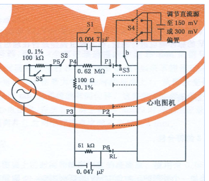
- Condition: Connect a parallel RC network 620k || 4.7nF in series with tested electrode,The idea is to compare the voltage level with and without series impedance. The difference must be less then 20% to pass the test.The test signal frequency 0.5H/10Hz/20Hz/100Hz.~~Here is the test circuit:
- Method:①ECG diagnosis equipment powers on,set the gain to 10mm/mV ②close S1&S2,set S3 to a, those used leads connet to P1 and P2, unused leads connect to P6,then regulate the sinusoidal signal generator to a 1Hz,20mm(peak-to-valley value) signal ③then disconnect S1,measure the change of amplitude.In the stable state,the change must be less then 20%. ④ Then use 0.5Hz,10Hz,20Hz,100Hz,and repeat step ①&②, The output amplitude's difference( disconnect S1 compared with connect S1) should be less then 20%.
Test results:

illustration:1. Sample rate is configured by the register of ADC1_ADS1298CONFIG1
2.Capacitance means the input capacitance of all channels, for example,C45、C46 in bellow picture:

3.pull-up resistor means the input pull-up resistor of all channels,for example,R49、R50 in above picture
4.for number 7 in above test results, R47 and R48 are shorted together~
From the test resuts,0.5Hz/10Hz/20Hz can pass the test in all conditions,but 100Hz cannot pass the test in any conditon~
Bisides, I have tested the EVM: ADS1298R, and test result is as followed:
100Hz 2mV signal,when the S1 is connected,the result is 1,91mV,and when the S1 is disconnected,the result is 1.96mV.
It means when external circuits is added,the peak-to peak value becomes larger. Compared with the original signal,their is distortion~
The register is configured as followed,and if you need the schematic,I can send you by mail~Hope I have made myself clear,If any problems,please let me know soon~thank you very much~
define ADC_CH_SET_ON_1 (0x0010u)
#define ADC_CH_SET_ON_6 (0x0000u)
#define ADC_CH_SET_ON_12 (0x0060u)
#define ADC_CH_SET_OFF (0x0090u)
#define ADC_CH_SET_MUX_OUT (0x0000u)
#define ADC_CH_SET_MUX_TSIG (0x0005u)
#define ADC_CH_SET_MUX_TMP (0x0004u)
//#define ADC_CH_SET ADC_CH_SET_ON_6 | ADC_CH_SET_MUX_TSIG
#define ADC_CH_SET ADC_CH_SET_ON_6
/* ADC 1 parameter data */
#define ADC1_TYPE ADS1298
#define ADC1_SERPORT (1)
#define ADC1_ADS1298DEVID (0x0000u)
//#define ADC1_ADS1298CONFIG1 (0x0085u)/* 采样率1000 */
#define ADC1_ADS1298CONFIG1 (0x0084u)/* 采样率2000 */
//#define ADC1_ADS1298CONFIG1 (0x0083u)/* 采样率4000 */
//#define ADC1_ADS1298CONFIG2 (0x0000u)/* 内部测试源 */
#define ADC1_ADS1298CONFIG2 (0x0015u)/* 内部测试源 */
//#define ADC1_ADS1298CONFIG3 (0x00DCu)
#define ADC1_ADS1298CONFIG3 (0x00EFu)
//#define ADC1_ADS1298LOFF (0x0003u)
#define ADC1_ADS1298LOFF (0x00E3u)
#define ADC1_ADS1298CH1SET ADC_CH_SET
#define ADC1_ADS1298CH2SET ADC_CH_SET
#define ADC1_ADS1298CH3SET ADC_CH_SET
#define ADC1_ADS1298CH4SET ADC_CH_SET
#define ADC1_ADS1298CH5SET ADC_CH_SET
#define ADC1_ADS1298CH6SET ADC_CH_SET
#define ADC1_ADS1298CH7SET ADC_CH_SET
#define ADC1_ADS1298CH8SET ADC_CH_SET
//#define ADC1_ADS1298RLDSENSP (0x0000u)
//#define ADC1_ADS1298RLDSENSN (0x0000u)
//#define ADC1_ADS1298RLDSENSP (0x0030u)
//#define ADC1_ADS1298RLDSENSN (0x0020u)
#define ADC1_ADS1298RLDSENSP (0x00FFu)
#define ADC1_ADS1298RLDSENSN (0x00FFu)
//#define ADC1_ADS1298LOFFSENSP (0x00FFu)
//#define ADC1_ADS1298LOFFSENSN (0x0002u)
#define ADC1_ADS1298LOFFSENSP (0x00FFu)
#define ADC1_ADS1298LOFFSENSN (0x0001u)
#define ADC1_ADS1298LOFFFLIP (0x0000u)
#define ADC1_ADS1298LOFFSTATP (0x000FFu)
#define ADC1_ADS1298LOFFSTATN (0x0003u)
#define ADC1_ADS1298GPIO (0x0001u)
#define ADC1_ADS1298PACE (0x0001u)
#define ADC1_ADS1298RESP (0x0000u)
#define ADC1_ADS1298CONFIG4 (0x0002u)
#define ADC1_ADS1298WCT1 (0x0009u)
#define ADC1_ADS1298WCT2 (0x00C2u)
//#define ADC1_ADS1298WCT1 (0x000Au)
//#define ADC1_ADS1298WCT2 (0x00E3u)


