Because of the holidays, TI E2E™ design support forum responses will be delayed from Dec. 25 through Jan. 2. Thank you for your patience.

This thread has been locked.

If you have a related question, please click the "Ask a related question" button in the top right corner. The newly created question will be automatically linked to this question.

ADS124S08: ADS124S08 Conversion abnormal issue during ESD test-Urgent and Important!!

Part Number: ADS124S08
Other Parts Discussed in Thread: TVS0500

Hi Team,

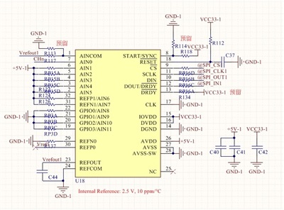
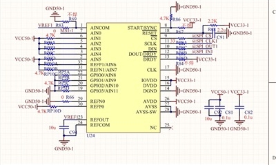
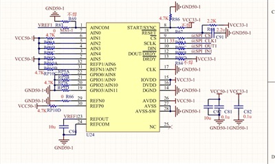
My customer is using our ADS124S08 in their project. When they doing the ESD test, ADS124S08 was found abnormal status. Firstly, pls find the schematic from below:

Start pin is pulled low, R114 installed and R118 uninstalled. For the PCB, Analog GND and Digital GND are using a single plane, this should be helpful for EMC test. 

During ESD test, +/-8.8kV contact discharge test on equipment, sometimes ADS124S08 will stop to output data normally. It was found ADS124S08's DOUT/DRDY pin will always high(busy status) and never low. We tried below:

1. If we try to read data from ADS124S08, all output 0.

2. Also we tried to send stop command and send start command again, it seems ADS124S08 is still in the wrong working status and still output 0.

3. We tried to read all the registers back from ADS124S08, all registers are correct and same with our initial value. This verify that ADS124S08's SPI interface is no problem, SPI communication is still good even in this abnormal status. Below are the registers:

Register Address Value
00h 08
01h 00
02h 0C
03h e8
04h 1a
05h 0a
06h 00
07h ff
08h 00
09h 11
0Ah 00
0Bh 00
0Ch 00
0Dh 00
0Eh 00
0Fh 40
10h 00
11h 00

4. If we want to escape from this abnormal status, we have to reset the ADS124S08 but the reset pin, after reset ADS124S08 and re-initial the ADS124S08, ADS124S08 will go back to normal status.

So based on above test, it seems the ESD noise makes part of  ADS124S08's digital circuit abnormal, maybe the conversion part, Now customer is planning to do pp, it is very urgent to solve and explain this issue, need application or design experts' support on this case! Can experts give help supporting this issue? Thanks a lot!

Best regards,

Sulyn

  • Hi Sulyn,

    Where in the circuit is the ESD discharge taking place? Most of the analog inputs are connected to the analog supply voltage. What is the resistance used in series with the input (R126 for example)? Has the RESET command been tried (instead of the reset pin)?

    What is connected to AIN0? Is there any series resistance to this input pin? Is there any external ESD protection to this input pin?

    So to accurately determine what might be happening we need to know how the discharge is getting to the device. Most likely if the digital portion is working but the analog is not, then the discharge is affecting the ADS124S08 either through the analog supply or the analog input pins (or perhaps a combination of both.) An 8kV discharge is much higher than the ESD rating for the device, so the supply and inputs must be adequately protected. The ESD rating for the ADS124S08 is primarily for packaging and handling the device in production only.

    As a number of the inputs are connected to the analog supply, any discharge that will directly impact the analog supply will also impact the ADS124S08. Most likely the analog supply should have a TVS diode to suppress a large voltage transient. Removing the analog input series resistors connected to the analog supply may show a benefit.

    As we do not know what is connected to AIN0, we do not know if that is a source for the transient getting into the ADS124S08. External ESD protection may be required here as well.

    Best regards,
    Bob B
  • Hi Bob,

    Thanks for the support! As for your questions, pls find my below answer:

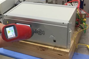
    1. ESD discharge will be randomly on the case of equipment. And the board in in the closed equipment(The equipment is metal case), see below example, he ESD gun will randomly inject the ESD energy on the equipment, but will not inject the ESD energy on the board directly because the board is in the closed equipment. Also the ESD is not inject on the power supply.

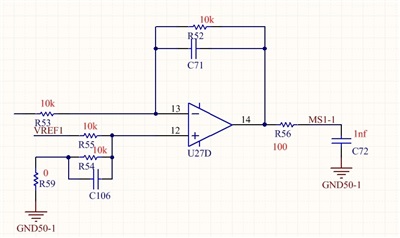
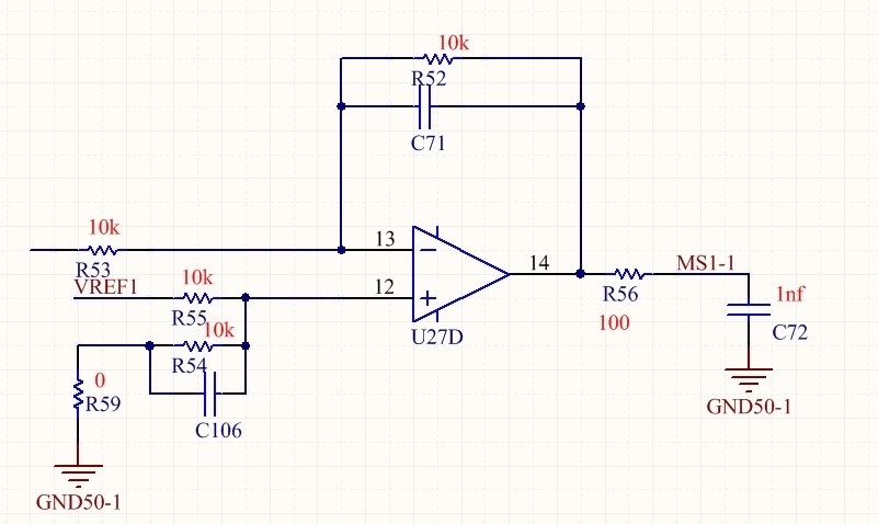
    2. For the parameters, pls find below schematic, and these is amplifier at front-end of ADS124S08, see MS1-1 showed below:

    Also these are EMC protection components at the front-end of amplifier, but as this is customer's  intellectual property, so they can't share with us. But this  protection components has been verified by many matured products with no problem.

    3. We tried to use Reset command, this command works and can let ADS124S08 turn back from abnormal status to normal status after send reset command and re-initial ADS124S08.

    So all above information for you. The phenomenon is when doing the ESD test, sometimes ADS124S08 will work abnormally, we can read configuration registers with no problem, but the output data is always o(DOUT/DRDY will always high, in busy status). Even we send the stop command and send start command again, ADS124S08 won't start to conversion again until we send Rest command and re-initial.

    Need your help to think about this and provide the solution, thanks.

    Best regards,

    Sulyn

  • Hi Sulyn,

    See my responses below.

    Best regards,

    Bob B

    Sulyn ZHANG said:

    Hi Bob,

    Thanks for the support! As for your questions, pls find my below answer:

    1. ESD discharge will be randomly on the case of equipment. And the board in in the closed equipment(The equipment is metal case), see below example, he ESD gun will randomly inject the ESD energy on the equipment, but will not inject the ESD energy on the board directly because the board is in the closed equipment. Also the ESD is not inject on the power supply. [Bob] How is the case connected to the PCB, and is there an earth ground connection of the case to the power source ground?  Ideally you want the case to shield the devices inside and shunt the ESD to earth ground.

    2. For the parameters, pls find below schematic, and these is amplifier at front-end of ADS124S08, see MS1-1 showed below:

    Also these are EMC protection components at the front-end of amplifier, but as this is customer's  intellectual property, so they can't share with us. But this  protection components has been verified by many matured products with no problem. [Bob] After discussing with the validation engineer, it may be that ADS124S08 is in a conflicted state if there was some energy applied to the START pin.  I would recommend that the R86 resistor be changed from 4.7k Ohm to 0 ohm.  This will directly tie this pin to GND.  The START pin supersedes the START command, so if this pin is in an invalid state due to the ESD, it may prevent the the START and STOP commands from working.

    3. We tried to use Reset command, this command works and can let ADS124S08 turn back from abnormal status to normal status after send reset command and re-initial ADS124S08. [Bob] This is is good news.  This truly means the digital communication is working and that the device will recover.  We now need to understand why the START and STOP commands are not functioning.  The first thing to do is to replace R86 with a 0 Ohm resistor.

    So all above information for you. The phenomenon is when doing the ESD test, sometimes ADS124S08 will work abnormally, we can read configuration registers with no problem, but the output data is always o(DOUT/DRDY will always high, in busy status). Even we send the stop command and send start command again, ADS124S08 won't start to conversion again until we send Rest command and re-initial.

    Need your help to think about this and provide the solution, thanks.

    Best regards,

    Sulyn

  • Hi Bob,
    Thanks for the support. We tried to change the pull down resistor to 0 ohm, these is still same. ADS124S08 will still behavior like this when doing ESD reset and won't recover even ESD test stopped unless send reset command. Any idea at you or team side for this issue?

    Best regards,
    Sulyn
  • Hi Sulyn,

    It is still not established how the ESD pulse is getting into the device. Mostly likely it is coming from the supplies or the analog inputs. As the digital portion still appears to work, it would appear that the digital supply and ground is ok. Next it should be determined if the problem occurs with the analog inputs or the analog supply. I would recommend a TVS diode be used on the analog supply for suppressing large transients from getting into the ADS124S08 through the analog supply. One possible example is the ON Semiconductor TVS diode ESD9D5.0ST5G.

    It may also be helpful to reduce the the value of C92. It is currently 10uF, which can store significant charge and may elevate the analog supply much longer than the transient itself. This could be reduced to a minimum of 330nF.

    There may also be something in the layout where are large inductance can sustain the voltage transient at a sensitive point on the ADS124S08. As I do not have the layout or the full schematic it is difficult to advise any further.

    To further troubleshoot the device, it would also be helpful to know if rewriting the register contents back to the ADS124S08 before a START command or RESET command will help bring the device back to proper operation.

    Best regards,
    Bob B
  • Hi Bob,

    I tried below actions and nothing works:

    1.  Add TVS, our TVS0500 at both AVDD(VCC50-1) and DVDD(VCC33-1) of ADS124S08, no improvement;

    2. Try to remove R56 and remove C72 as showed in the input path, then short C72 to GND directly, then do the ESD test. No improvement.

    3. Try to reduce the cap of C92 to 470nF(As no 330nF found), no improvement;

    4. As customer can't accept to add safety cap between GND of ADS124S08 and Earth(In order to avoiding ground loop), so we can't add safety here;

    Really don't know how to improve or solve this issue? Below is the layout, you can help check if these is any issue?

    PCB.zip

    BTW, would any possible that we tried to do ESD test in TI Lab(I think you don't need to exact same with my customer's condition. Just test TI EVM even with TVS/ESD protection, then do the test, you may found ADS124S08 die and need soft reset or hardware reset to recover), I believe we may found this issue too. This is important for TI future products and compete with competitor, Thanks a lot. We need your great support on this.

    Best regards,

    Sulyn 

  • Hi Sulyn,

    It is difficult to suggest a clear solution without knowing for sure where the ESD is getting into the device. From the layout, there appears to be a good and adequate ground. As I have stated before, the most likely place for the ESD to get into the device is through the digital or analog signals or supply.

    The ESD clamp using the TVS0500 does not start to clamp before 7.9V (see section 9.2.2 of the datasheet). This is not good enough. You need to use a TVS diode with characteristics the same or similar to ESD9D5.0ST5G. This diode should be on both the analog and digital supplies close to the ADS124S08 supply pins.

    I would highly recommend that the entry points for the ESD to be limited by removing the resistor networks on the unused analog pins. This would limit the ESD occurrence to the digital inputs and the supply pins only. Once we know for sure where the ESD is getting into the device, it is easier to find a good solution.

    Best regards,
    Bob B