This thread has been locked.

If you have a related question, please click the "Ask a related question" button in the top right corner. The newly created question will be automatically linked to this question.

ADS1298: Can I use RLD as the negtive input of the PGA?

Part Number: ADS1298

For the chest leads of the standard 12 leads connecting, the WCT is used as the negtive input of the PGA.

WCT is the average of LA\RA\LL, and it is used as a relatively stable reference.

And I want to use the average of all the electrodes to replace the WCT.

In the ADS1298 EVM, the RLDOUT is feedthrough to the RLDIN. And I configure the MUXn of register CHnSET to '111 = RLD_DRN (negative electrode is the driver)'

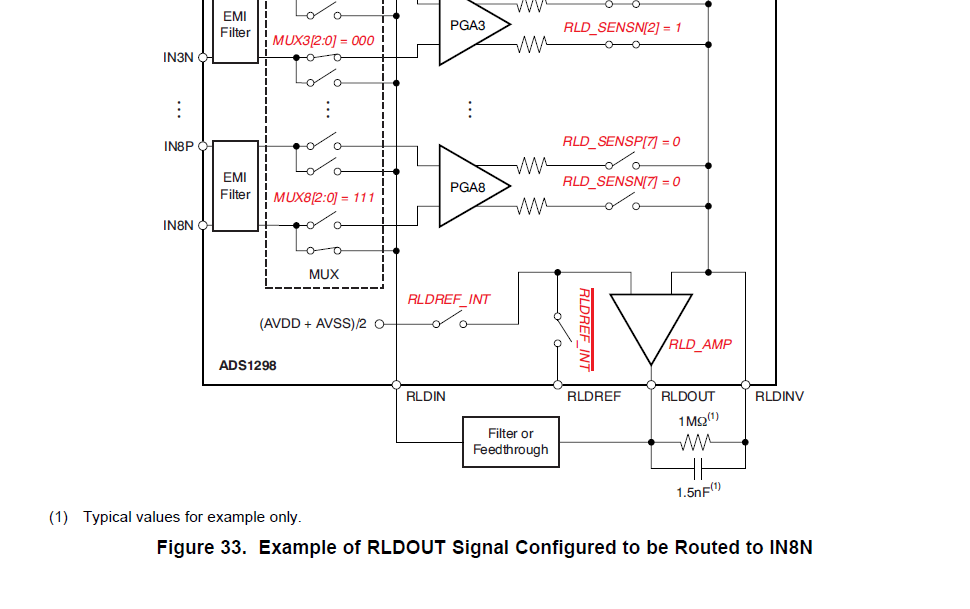
And I configure the RLD_SENSP=0xFE, RLD_SENSN=0x04, which means the RLD=CH2P+CH3P+CH3N+CH4P…+CH8P (the average of all the Electrodes).

Here is the configuration:

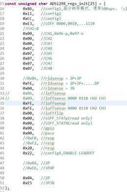
I think the above configuration makes the negtive input of the PGA be the average of all the Electrodes.

But the captured data shows only white noise:

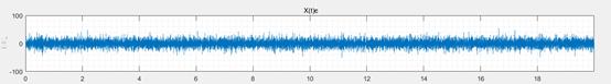
Is there any mistake in the above idea?

Thank you.

  • Hi Frank,

    Thanks for your post!

    If you're averaging all of the electrodes together then the positive nodes will cancel out the negative ones. Why do you want to average all of the electrodes instead of LA\RA\LL?

    This thread may help: e2e.ti.com/.../2583424
  • Hello Frank,

    When MUXn[2:0] = 111, the voltage on RLDIN is routed to the negative input pin of that channel. At the same time, both input pins for that channel are disconnected from the PGA. The PGA inputs are basically floating and the channel cannot be used to measure data or for RLD common-mode derivation.

    Also, keep in mind that the RLD output will have an inverse phase relationship to the other input channels. Depending on what you wish to measure, you may consider inverting the RLD output before applying the signal to the negative channel inputs.

    My recommendation would be not to use MUXn[2:0] = 111 and route the RLD output externally (with or without the inverting buffer) to the negative channel inputs. This way, the positive electrodes can still be used for RLD derivation and the channel output will have valid data.

    Best Regards,

  • Hi Alexander Smith,

         Thank you very much for reply.

         There are many Lead Systems, such as the STANDARD 12 LEADS SYSTEM and the FRANK LEAD SYSTEM.

         The WCT is used in the STANDARD 12 LEADS SYSTEM.

         In my system, I want to use another Lead System, and I want the negtive nodes to be the average of IN2P/IN3P..../IN8P.

    Frank

  • Hi Ryan Andrews,

         Thank you very much!

         I will try the external connection.

         And, what is the gain of the RLD_AMP? And, what is the gain of the WCT_AMP?

         Since I want INxN = the avergage of IN2P/IN3P....IN8P, I am afraid if the gain of the RLD_AMP is too large, the gain*(avergage of IN2P/IN3P....IN8P) may not be a good reference. In that case, I will have to use external operational amplifiers and resisters to generate a 1*(avergage of IN2P/IN3P....IN8P) to be used as reference.

         Do you have any suggestion on the gain range to generate a good reference?

         Thank you.

    Frank

  • Hi Frank,

    The gain for the RLD amplifier can be found using equation 3 of this document: www.ti.com/.../sbaa188.pdf

    Rcm will be 220k in parallel 8 times since you are using 8 channels to generate the inverting input.
    220k || 220k ||.......||220k

    The gain of the WCT_AMP is fixed at 1, however keep in mind that it averages of the input signals.
  • Hi Alexander Smith,
    Got it. Thank you so much!
    Frank