This thread has been locked.

If you have a related question, please click the "Ask a related question" button in the top right corner. The newly created question will be automatically linked to this question.

ADS1248: IDAC current problem

Part Number: ADS1248

I am having trouble reading from RTDs. All reads return a 7FFFFF value. No voltage can be read across the RTDs leading me to believe the IDAC current is not outputting. I tried adding an ammeter in the line and read no current either. 

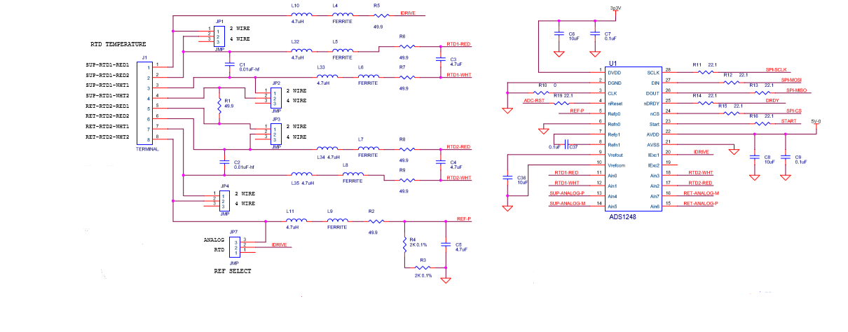
Here is the circuit we are using on our pcb: 


and the process is:

Power up

set reset pin high

wait 16ms

write reset opcode 

wait 1ms

write SDATAC opcode

write register values

Reg 0 MUX0      = 0x01 (Burnout off, ADC positive input = AIN0, ADC negative input = AIN1 )

Reg 1 VBIAS      = 0x00 (VBIAS off)

Reg 2 MUX1      = 0x20 (Internal reference always on, REFP0 and REFN0, Normal operation)

Reg 3 SYS0        = 0x14 (PGA =2, Data rate = 80)

Reg 4 OFC0       = 0x00 (No offset)

Reg 5 OFC1       = 0x00 (No offset)

Reg 6 OFC2       = 0x00 (No offset)

Reg 7 FSC0        = 0x00 (Gain set by PGA to 0x402000)

Reg 8 FSC1        = 0x02 (Gain set by PGA to 0x402000)

Reg 9 FSC2        = 0x40 (Gain set by PGA to 0x402000)

Reg a IDAC0      = 0x94 (Data out only, IDAC magnitude = 500uA)

Reg b IDAC1      = 0x8F (IDAC1 = IEXC1, IDAC2 = Disconnected)

Reg c GPIOCFG = 0x00 (NO gpio)

Reg d GPIODIR  = 0x00 (NO gpio)

Reg e GPIODAT = 0x00 (NO gpio)

pulse start pin high for 20us

wait for drdy interrupt

send RDATA opcode followed by 24 clocks


I have double checked the initialization several times and it seems right to me, but I cannot measure any excitation current or voltage across the RTDs. I also tried IEXC2 with a resistor to ground. Am I doing something wrong? Are there any problems with the circuit? Also I mistakenly set REFSELT[1:0] to Internal reference selected and internally connected to REFP0 and REFN0 pins, is it possible this damaged the current supply?


  • Dorian,


    Generally, 7FFFFF value means that the ADC is reading a full scale. This could be that the inputs are open, or it could mean that the reference is basically 0. Regardless, it's an indication that the input voltage is larger than the reference (with gain included).

    For the time being, I'm going to assume that you are correctly communicating with the device. It looks like you're reading data from the device correctly, verifying the FSC registers, and using the SDATAC command. However, if there are communication issues, I highly recommend using an oscilloscope or logic analyzer to look at the SPI lines.

    For now, I would guess this is a connection problem. You didn't go through your connections on your board, but I assume that you're measuring a 4-wire RTDs. Can you show all your connections that you're using? I'd like you to trace out the current path from the IDRIVE of IEXC1, through your RTD connections and jumpers, to the reference resistor, and then to ground. If you had missed a connection, or there's an unintended break, then the current stops, and you get no current at all.

    As an alternate test, you can disconnect everything from J1 and use JP7 and rout your current through to the reference resistors R3 and R4. This way you could determine that the IDAC current can be turned on and adjusted.

    As for your last comment, I don't think it's likely that you damaged the current supply with the internal reference selection. I would just check the connections and start there.


    Joseph Wu
  • Joseph,

    Thanks for the idea to jumper JP7. It significantly simplified our diagnosis. We were not getting any current from IEXC and we were able to trace it back to a bad connection at the VREFOUT capacitor. A little bit of solder and we are working well now.