Because of the Thanksgiving holiday in the U.S., TI E2E™ design support forum responses may be delayed from November 25 through December 2. Thank you for your patience.

This thread has been locked.

If you have a related question, please click the "Ask a related question" button in the top right corner. The newly created question will be automatically linked to this question.

ADS131E08: poblems with capturing the sine wave in xilinx chipscope!

Part Number: ADS131E08

Hello guys,
I designed a Data Acquisition system with ADS131e08 ADC and spartan6 FPGA.
I config the ADC and read data from it by my vhdl code that it contains several States. In this states, the ADC first reset and then the Config registers sets correctly.
I use xilinx Chipscope to capture the received data. when the Analog input of ADC is set to DC values, the received data in chipscope is correct and no problems, but when analog input connected to AC value(sine wave), the received data is not sine.
I set the ADC parameters to:
Fclk= 2.048 MHz
Fsclk = 18.432 MHz
Fchipscope= 2* Fsclk
Data Rates : 1KSPS
RESOLUTION = 24bit
AVDD = +2.5v
AVSS = -2.5v
sine Wave (peek to peek = 4v) that is less than the ADC Vp-p = AVDD - AVSS.

I guess the problem is related to the Chipscope settings?Rights?
Please help me to solve this problem.
regards,

  • Hello Javad,

    Thank you for your post.

    Do you have a way to plot the raw data or save it to a text file and share it? And what is the frequency of the input sine wave?

    Please share the complete register settings of the ADS131E08.

    Best Regards,

  • Hello Ryan,

    Thank you for reply.

    The ADC Registers are:

    CONFIG1 = 0xD6 , CONFIG2 = 0xF0 , CONFIG3 = 0xC0

    CH1SET = 0x10 , GAIN1 = 1 , MUX1 = 000 (normal input) 

    CHnSET = 0x90 , n = 2...8 this channel power downed

    and

    Fclk = 2.048 MHz

    Fsclk = 18.432

    I change the Fchipscope to new value that produced by this manner:

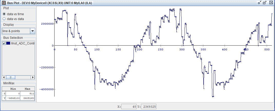
    I use sine wave with frequency 50 Hz that period of it is 20ms. I sample the sine wave 256 times with ADC that total frequency is 256 x 50Hz. I produce this frequency by counter and send it to the Xilinx ChipScope and received data is semi-sine wave (below figure) and should be sine wave because of ADC resolution (24 bit).

    I use oscilloscope to saw the sine wave that Vp-p of it is whole 4v that is safe and less than the ADC inputs Vp-p. 

    Please help me to find the problem and ADC capture the sine wave correctly.

    best regards,

  • Hi Javad,

    What do you mean when you say that you sample the sine wave 256 times? CONFIG1 = 0xD6 means you have set the output data rate to 1 kSPS. However, if you say that you're reading the data 256 times per 50-Hz cycle, that means you are reading at 12.8 kSPS. Are you using the RDATAC mode or the RDATA mode?

    Please review section 9.4.5.2 of the datasheet. In RDATAC mode, data must be collected in between consecutive /DRDY falling edges. In RDATA mode, you may issue the RDATA SPI command any time, and the most recent conversion result be loaded into the output shift register. 

    Another question: what is your DVDD supply voltage? Please note that for DVDD < 2.0 V, the minimum SCLK period is 66.6 ns. Currently, your SCLK period is only 54.25 ns.


    Best Regards,

  • Hi Ryan.

    Thank you for reply.

    I set the CONFIG1 = 0xD2 and use the RDATA mode and set the VDD=3.3v that SCLK is 54 ns.

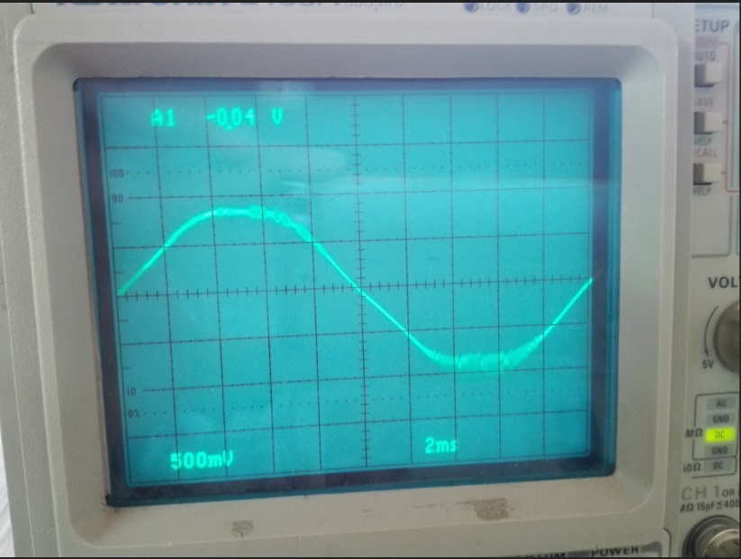
    Also i use the sine wave with Vp-p=2v that i check it by oscilloscope, when i connect the ADC board to the power, it inject the noise to the sine wave and change the peaks of it(the figure captured by oscilloscope has shown), but when i disconnect the ADC board, the noise removed and sine wave be corrected.

     When i captured the Data by Xilinx Chipscope, the received data is similar to the sine wave but not exactly sine and has distortion (ans this ADC is 24 bit and must be exact to capture the input and display it).

    I use the ADS131e08 evaluation board schematic to design the board that pdf of schematic has uploaded.

    ADS131_schematic.pdf

    please help me to solve the problems(remove the injected noise and receive and capture the sine wave exactly).

    best regards.

  • Hi Javad,

    Most likely, there is some noise that is injected onto the ground plane from the Xilinx Chipscope that is coupling onto the ADC board and onto the oscilloscope. Make sure you have a good connection between the ground planes of each board and between the oscilloscope ground.

    The results above do not appear to be sampled at a consistent sampling rate. For AC applications, it is more appropriate to use RDATAC mode and ensure you can read all the data between samples. Start with a slow data rate at first.

    Best Regards,