Other Parts Discussed in Thread: ADS1292
Hi everyone,
I purchased an ADS1292 ECG evm board for debugging. Our development platform is NXP RT1050. Because ourselves hardware is not ready yet, I used a RT1050 EVM board to connect the ADS 1292 on the
ADS1292 ECG evm board.
The connection is like this: disconnect these ADS1292 pin from the MSP430: DRDY, DOUT, SCLK, DIN, CS, START, PWDN/RESET. Connect these pin to the RT1050 EVM board. Also instead of supply power using microusb, connect two line from the RT1050 EVM to the USB port to supply power.
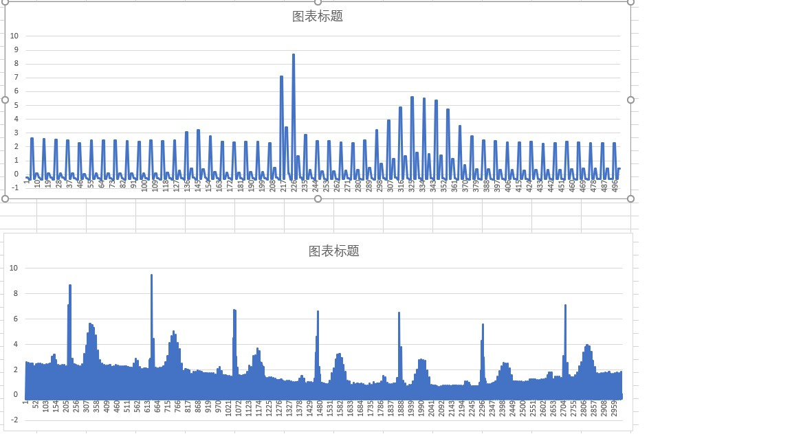
1. After connect a ECG simulator to the ADS1292 EVM, I debug in the RT1050 board to communicate with ADS1292. When the DRDY interrupt is trigger, the ECG data can be read from SPI. But some of the data seem to be incorrect. For example, the packet like this, C0 00 00 7F FF FF 80 00 00, this means the measure voltage is out of VREF voltage.
2. On the RT1050EVM, I can send ADS1292_START and ADS1292_STOP command successfully. The ADS1292 response the two commands. But other commands such as ADS1292_RDATAC, ADS1292_SDATAC, ADS1292_RREG, it seems ADS1292 has no response on these commands.
Does my connection of ADS1292 on the MSP430 EVM have any fault? Or some other pins should also connected to the RT1050?
Please give some advice if any.
Thank you very much.