This thread has been locked.
If you have a related question, please click the "Ask a related question" button in the top right corner. The newly created question will be automatically linked to this question.
Hi all,
we are using an ADS124S06 and we notice a problem with Data Ready signal. We are working at 50 sps.
In particular we use the GPIO of the chip in order to drive some transistor. We noticed that everytime we write to the GPIODAT register the converter seem to start another unwanted conversion cause the Data Ready signal unexpectedly stay high for a variable time (from 10 ms up to 14 ms) and then come back to low regularly.
We correctly write the GPIODAT register by issue the command 0x50 and the relative data.
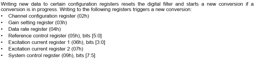
We know that writing to certain registers could affect Data Ready as stated in your datasheet (see attachement) but writing to GPIO registers should not affect the Data Ready signal because it should not trigger a new conversion.
Do you have any idea of this behaviour?
Thank you in advance
Best regards
Hi PLCmatic,
Changing the GPIODAT register should not affect the conversion. Can you send me the configuration register settings you are currently using, and the value your are writing to the GPIODAT register?
Writing a register will force DRDY high as shown in Figure 92 of the ADS124S06 datasheet.
Best regards,
Bob B
Hi PLCmatic,
After DRDY transitions from high to low state, DRDY will return high following the first SCLK. DRDY will remain high until the next conversion completes. If the conversion ends during a communication cycle (such as a WREG) DRDY will go and remain low through the duration of the communication. Once the SPI bus returns to an idle state, the next SCLK will return DRDY high.
You have the device configured as continuous mode. It is not clear if you are using the START pin, or the START/STOP commands. Let's assume you are using the START/STOP commands. Issuing the first START command will begin conversions. As you have selected 50sps data rate, you should see the DRDY pin pulse approximately every 20ms (assuming no register writes or reads and no data is read following conversion).
When you write new register contents to the GPIODAT register, the beginning of the WREG command will force DRDY high. The timing from the previous transition from DRDY from high to low and the next DRDY transition to low should maintain the period of 20ms. According to the original post the timing between the command and DRDY falling was from 10 to 14ms. This would seem to be as expected since a new conversion has not started and the total conversion time is 20ms.
It is possible to control the start of conversion by sending back to back commands of the STOP command followed by the START command. If you need a delay after setting the GPIO pin, I would suggest issuing the STOP command, then delaying and following the delay issue the START command. Note that if a conversion is taking place at the time of the STOP command, the conversion will continue until the conversion has completed.
If you still are unsure of what is happening, send me scope/logic analyzer shots of the communication including DRDY. One other thing I noticed is that you have GPIO0 set as high, but the pin is configured as disabled. Are you using GPIO0 or one of the other GPIO pins on the ADS124S06?
Best regards,
Bob B
Hi Bob,
this one
"When you write new register contents to the GPIODAT register, the beginning of the WREG command will force DRDY high. The timing from the previous transition from DRDY from high to low and the next DRDY transition to low should maintain the period of 20ms. According to the original post the timing between the command and DRDY falling was from 10 to 14ms. This would seem to be as expected since a new conversion has not started and the total conversion time is 20ms."
covers all our doubts!!!
Thanks for your preciuous help.
Best regards