Other Parts Discussed in Thread: TIDA-00317,
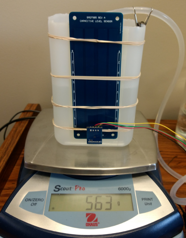
I'm using the FDC1004EVM module with the TIDA-00317 design (modified for a .034" thick rigid PCB) attached to a plastic square bottle using 3M adhesive.
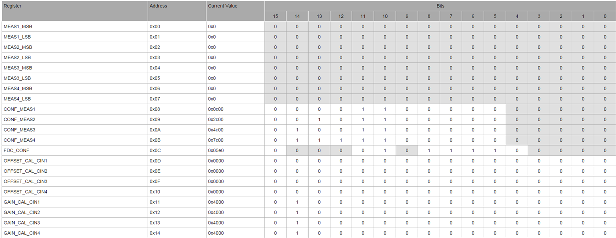
I set up a system that will automatically pump back and forth between two vessels while simultaneously recording data from capacitive level sensor and a lab scale that the bottle is placed on top of. The FDC1004 is configured as follows:
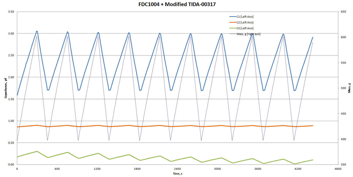
If I do a basic measurement (C1/C2), the sensor is pretty steady and tracks the liquid level pretty well. However I cannot use the environmental reference electrode because it causes the liquid level measurement to be inaccurate and drift, see the following data:
I believe there are two problems with the reference electrode:
- The capacitance of the reference electrode changes with the liquid level. I believe this is because the trace that goes to the reference electrode positioned in a way on the TIDA-00317 such that the capacitance of the trace is affected by the liquid level. I can resolve this with a simple design change.
- The capacitance of the reference electrode is drifting downward over time. The drift of the reference electrode causes a drift in the level measurement approximately equivalent to 1.2 cm per hour. I have very little idea what could be causing this. Our best guess is that it relates to how the shields are set up on the TIDA-00317. Referencing Figure 12 and section 8.3.1 in the FDC1004 datasheet, CIN1 and CIN2 are referenced to SHLD1, while CIN3 is referenced to SHLD 2 when doing a differential measurement. However, the TIDA-00317 is set up such that CIN2 (reference liquid) and CIN3 (reference environment) are both backed by SHLD1. Is this intended? I may be misinterpreting the datasheet. If this isn't a problem, what else could be causing this drift in the reference electrode output?
Thanks,
Sam


