This thread has been locked.

If you have a related question, please click the "Ask a related question" button in the top right corner. The newly created question will be automatically linked to this question.

ADS1262: Converted result isnt satisfied even analog inputs connected to testdacs.

Part Number: ADS1262

To whom Related,

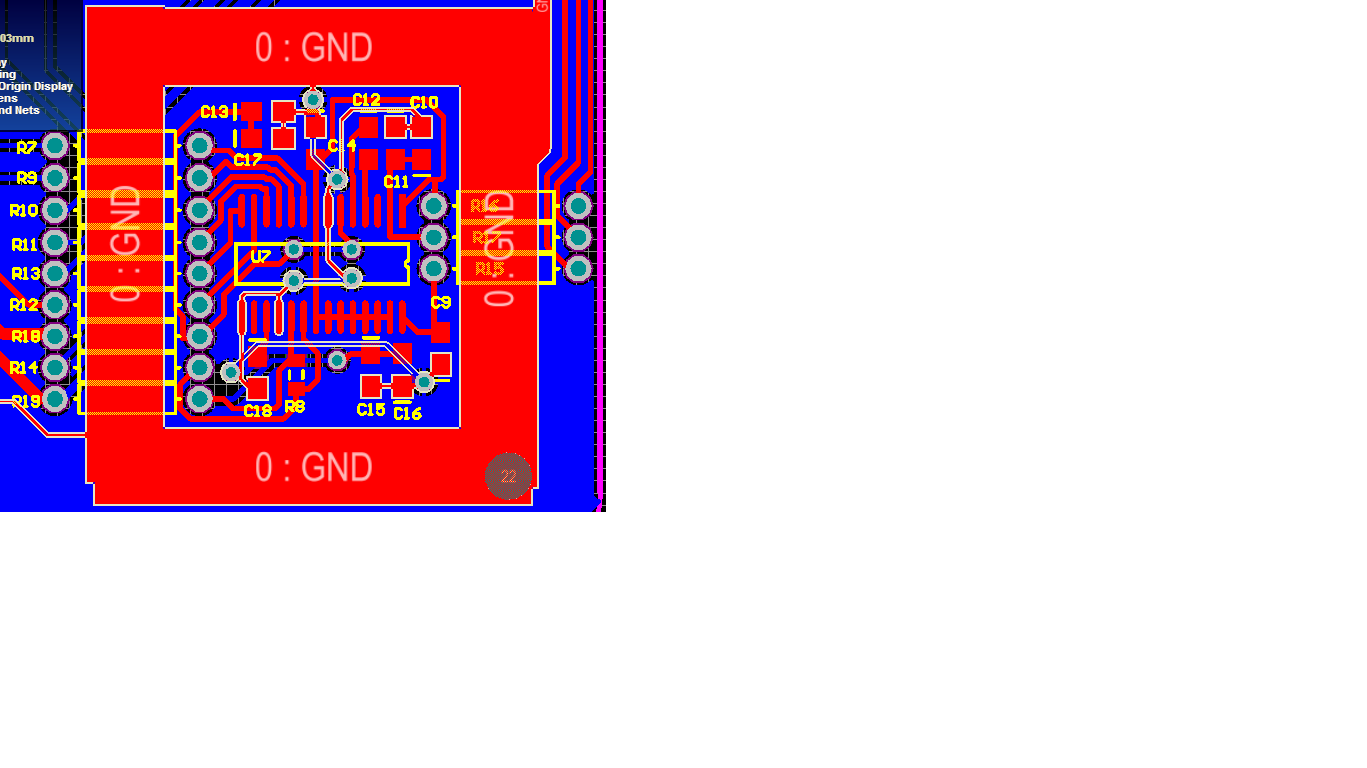
My name is celal. My circuit is included in ads1262, analog gyroscope(adxrs624) and esp8266 arduino board. Connections and pcb layout of ads1262 as attached. I use a generic codes from this forum as below.

ads1262_Reg_Write(POWER, 0x11);delay(10); //11h (default) internal ref enabled
ads1262_Reg_Write(INTERFACE, 0x0D);delay(10); //05h (default) Status byte enabled, Checksum enablade
ads1262_Reg_Write(MODE0, 0x00);delay(10); //00h (default) Continuous Conv Mode | 0x40 Pulse conversion mode (one shot conversion)
ads1262_Reg_Write(MODE1, 0x00);delay(10); //80h (default) FIR Filter | 00h sinc1 | 60h sinc4
ads1262_Reg_Write(MODE2, 0x89);delay(10); //04h (default) PGA enabled 1V/V 20sps| 5Ch 32V/V 7200sps | 5Fh 32V/V 38400sps
ads1262_Reg_Write(INPMUX, 0xEE);delay(10); //01h (default) Multiplexer, AIN0 e AIN1 | 23h AIN2 e AIN3
ads1262_Reg_Write(OFCAL0, 0x00);delay(10); //00h (default) Offset Calibration Registers
ads1262_Reg_Write(OFCAL1, 0x00);delay(10); //00h (default) Offset Calibration Registers
ads1262_Reg_Write(OFCAL2, 0x00);delay(10); //00h (default) Offset Calibration Registers
ads1262_Reg_Write(FSCAL0, 0x00);delay(10); //00h (default) Full-Scale Calibration Registers
ads1262_Reg_Write(FSCAL1, 0x00);delay(10); //00h (default) Full-Scale Calibration Registers
ads1262_Reg_Write(FSCAL2, 0x40);delay(10); //40h (default) Full-Scale Calibration Registers
ads1262_Reg_Write(IDACMUX, 0xBB);delay(10); //BBh (default) Output Multiplexer, no connection, no connection
ads1262_Reg_Write(IDACMAG, 0x00);delay(10); //00h (default) Current magnitude, off
ads1262_Reg_Write(REFMUX, 0x00);delay(10); //00h (default) Reference Multiplexer, 2.5V, 2.5V
ads1262_Reg_Write(TDACP, 0x00);delay(10);//00h (default) TDACP, no connection
ads1262_Reg_Write(TDACN, 0x11);delay(10); //00h (default) TDACN, no connection
ads1262_Reg_Write(GPIOCON, 0x00);delay(10); //00h (default) GPIO not connected
ads1262_Reg_Write(GPIODIR, 0x00);delay(10); //00h (default) GPIO output
ads1262_Reg_Write(GPIODAT, 0x00);delay(10); //00h (default) GPIO low
ads1262_Reg_Write(ADC2CFG, 0x00);delay(10); //00h (default) ADC2
ads1262_Reg_Write(ADC2MUX, 0x01);delay(10); //01h (default)
ads1262_Reg_Write(ADC2OFC0, 0x00);delay(10); //00h (default)
ads1262_Reg_Write(ADC2OFC1, 0x00);delay(10); //00h (default)
ads1262_Reg_Write(ADC2FSC0, 0x00);delay(10); //00h (default)
ads1262_Reg_Write(ADC2FSC1, 0x40);delay(10); //40h (default)
SPI.transfer(START); 

I selected test dac to analog inputs  like positive is 2.5V and negative is 2.4921875V as per at the datasheet.The difference is about  7.8125 mV.  I got result from 7.84 mV to 8.15 mV.  simple span=((8.15-7.84)/(8.15+7.84)/2)*100=4%

I expected 0.4%of  simple span but  adc output  ten times grater than expected.

Can you suggest any tips or tricks about improve the result?

 pm_sch.pdf

  • Hi Celal,

    Welcome to the TI E2E Forums!

    From your register configurations it looks like you are programming the MODE2 register to "0x89", which bypasses the internal PGA. This setting in particular might be increasing the observed gain error since it requires that your source's output impedance be very low to be able to drive the ADC inputs directly.

    The internal test DAC is a resistor string that does not have a low output impedance, so I would recommend enabling the PGA (i.e. by changing the MODE2 register setting to "0x09") when measuring the Test DAC signal.

    Try that modification and see if it helps.

    Best regards,
    Chris
  • Thank you for your quick reply,

    I tried with enabled PGA and my description simple span is shortened to 7.98 - 8.11mV. Is there anything to  avoid from this fluctuation  at 1200 SPS? 
    On the other hand, I want to see that only performance of ads1262 to measure precision enough if the signal comes the clearest way. I think that pcb and other conditions are not dominant effect when i measure the test dacs. Indeed  same fluctuation is available for signal comes from my gyroscope. As you can see, discrete LDOs are supplying the digital and analog sides, all adc circuit is rounded ground and there is massive ground plate at the bottom side of pcb and analog and digital signals are feeded to chip seperately.I will also put a cover and solder to front side pcb. I think that, these are enough to operate chips in datasheets parameters.
    According to datasheet if i select 1200 sps Sinc4 filter, internal noise is about 13.4 uVpp. When i measure the test dacs, should i see 7.98x mV every measuring cycle? 
    Kindly request your reply.
    Bst Rgds,
     
  • Hi Celal,

    The internal test DAC is probably not the best source for determining ADC accuracy or noise performance. Its purpose was more intended to be used as a quick and crude functionality test rather than a precision voltage source. Being that the test DAC is a resistor string connected between the AVDD and AVSS supplies, it is very susceptible to power supply noise.

    For noise performance tests, I would start by shorting the ADC inputs together, as this is a similar test condition to the noise performance specifications in the datasheet. To ensure  a proper common-mode voltage, I would recommend shorting the inputs to AINCOM and enabling the VBIAS level-shifter. If you do not see 13.4 uVpp or less at the 1200 SPS, SINC4 configuration with the analog inputs shorted then probably there is some additional power supply or layout noise that coupling into the measurement.

    Regarding your layout, it is very good for a 2-layer PCB. If anything could be improved I would suggest...

    1) Try to connect the supply decoupling capacitors to the ADC with much shorter traces (and avoiding vias, if possible). The longer the connecting traces, the less effective the decoupling filters will be; and...

    2) Being a 2 layer board, the bottom layer is essentially your ground plane. As much as possible, try to avoid routing traces on the ground layer as they create splits in the ground plane, which in turn tends to increase the ground plane impedance and may lead to additional common impedance coupling of noise into your signals.

    In the case of your larger vias, they also create a ground plane split. If you can slightly decrease the vias sizes or space them out a bit more so that the ground plane is able to flow between vias, that would be advisable.

    I hope that helps,
    Chris