Hi
please see the new reply on this post.
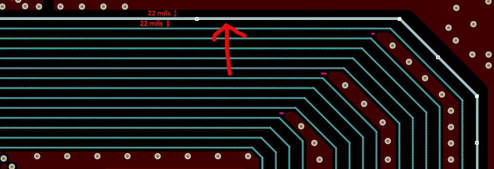
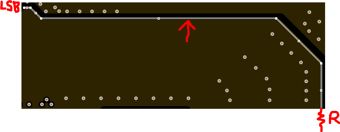
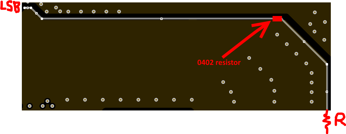
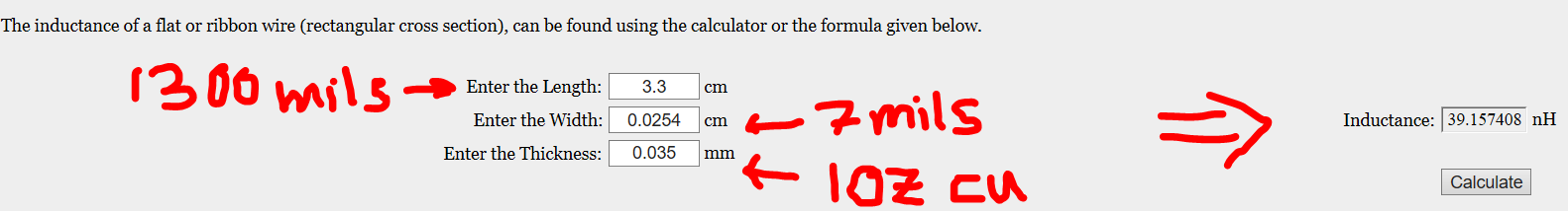
I have ordered my PCB to a Chinese PCB manufacture, once in one of PCB modifications for the PCB manufacture, the ground plane was removed a little under LSB line of the DAC
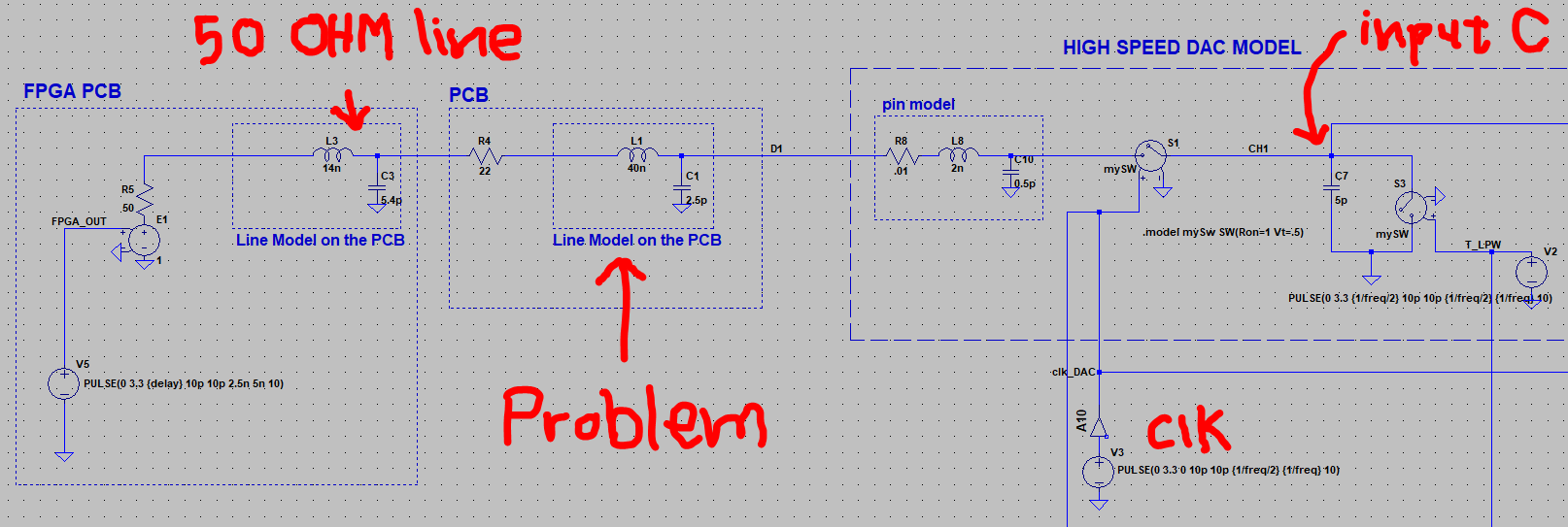
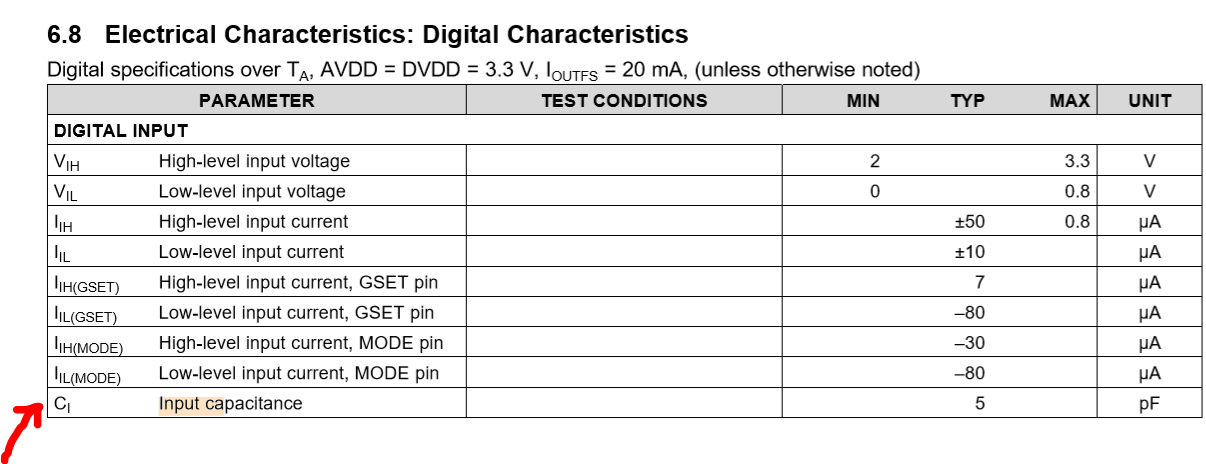
as you see in the following picture the input capacitance is 5pF but how much the input resistance of the input is?
Best Regards