This thread has been locked.

If you have a related question, please click the "Ask a related question" button in the top right corner. The newly created question will be automatically linked to this question.

ADS1298R: ADS1298R

Part Number: ADS1298R

Hello,

I have some doubts regarding RL Lead -off Detection. I am using ADS1298R.

We have status Bits for Lead -off Detection as per below:

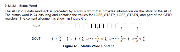
As per that we are getting status update for 8 channels at every sample.for this 8 channels we can derive status of V1 to V6 RA,LA,LL.

But  for RL Lead-Off what should be done??

How can i detect RL Lead off at every sample?? Please suggest method for it.

  • Hello Saloni,

    Thank you for your post.

    The RLD lead-off status bit is only reported in the CONFIG3 register (Bit 0 = "RLD_STAT"). You would have to read this register with a RREG command in order to read the value of the comparator on the RLD output. You would not be able to do this every sample.

    Unfortunately, continuous-time RLD lead-off detection is not easily done with the ADS1298R. The comparator is connected directly to the output of the RLD amplifier. This node is always driven to a known voltage when the RLD amplifier is turned on, even when the RLD electrode is disconnected from the subject. This was an oversight in our design that we hope to address in the future.

    Best Regards,
  • Thank for your answer.

    As per observation when RL is removed all the Positive Leads show Lead-off Status,i.e. IN8P to IN1P all are raised to status 1.

    LOFF_STATP[7:0] gives OXFF. 

     When we are removing only RL lead in RDATAC mode, it affects other leads, observed status word on that time is 0xCF 0xF0 0x00, can we use this status word bit pattern to derive that RL lead is off, suggest?

  • Hello Saloni,

    Yes, I think that is the best approach with the ADS1298R. Essentially, if the lead-off current sources are unbalanced (i.e. more LOFFP bits are enabled than LOFFN bits), then the inputs will be pulled in the same direction when RLD is disconnected from the body. The more unbalanced you make the lead-off current, the more reliable this method will be.

    How do you have the LOFF_SENSP and LOFF_SENSN registers configured in your tests?

    Best Regards,
  • Thank you for your Response.

    I have configured LOFF_SENSP & LOFF_SENSN both as 0XFF.