This thread has been locked.

If you have a related question, please click the "Ask a related question" button in the top right corner. The newly created question will be automatically linked to this question.

ADS1299: Noise in the normal mode and ID register

Part Number: ADS1299

When I read the Device ID it gives me 0xDF but for the ADS1299 should end in E instead of F. Why this happen? Is there something wrong if I get 0xDF?

I'm using the internal clock and 250 samples per second.

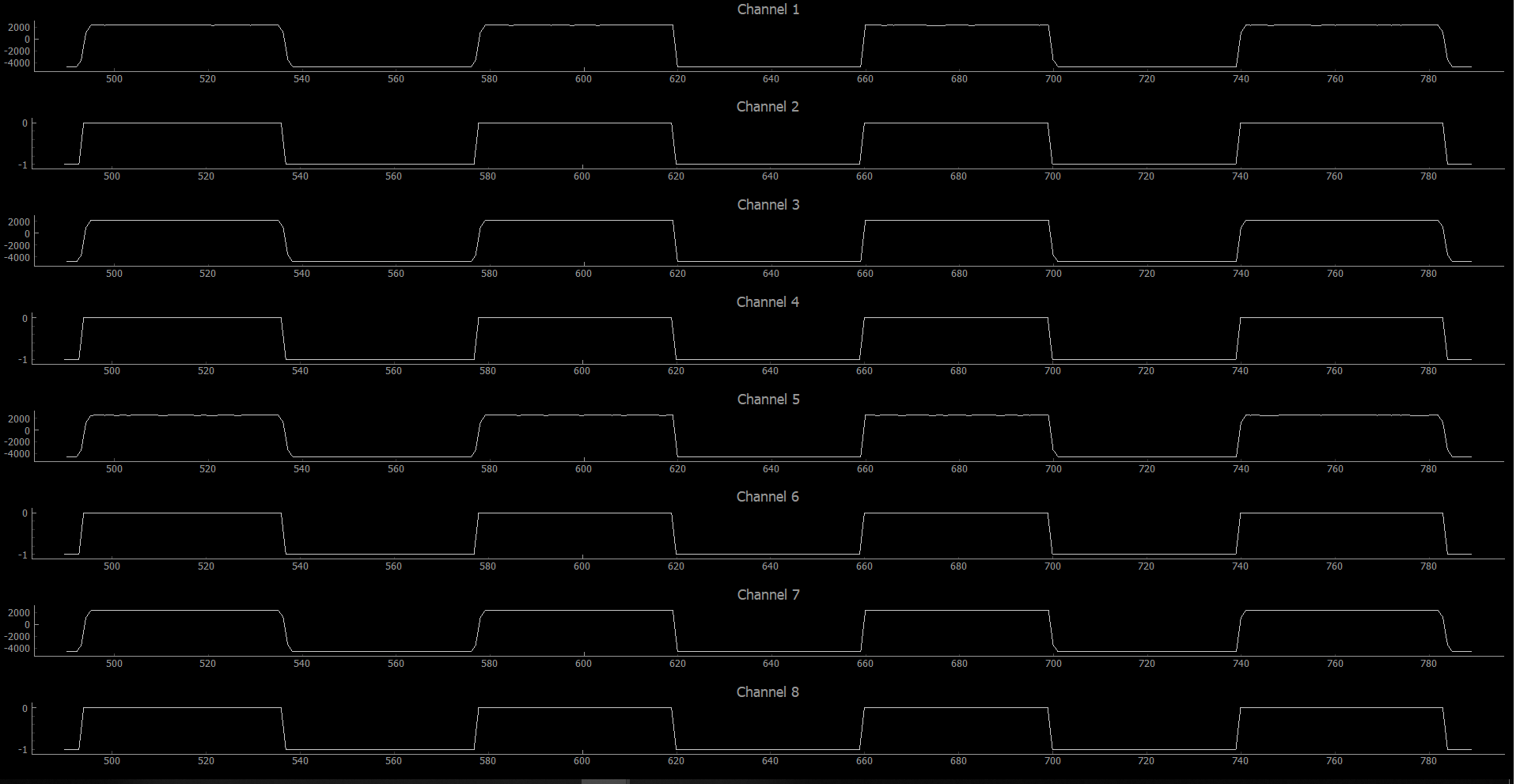
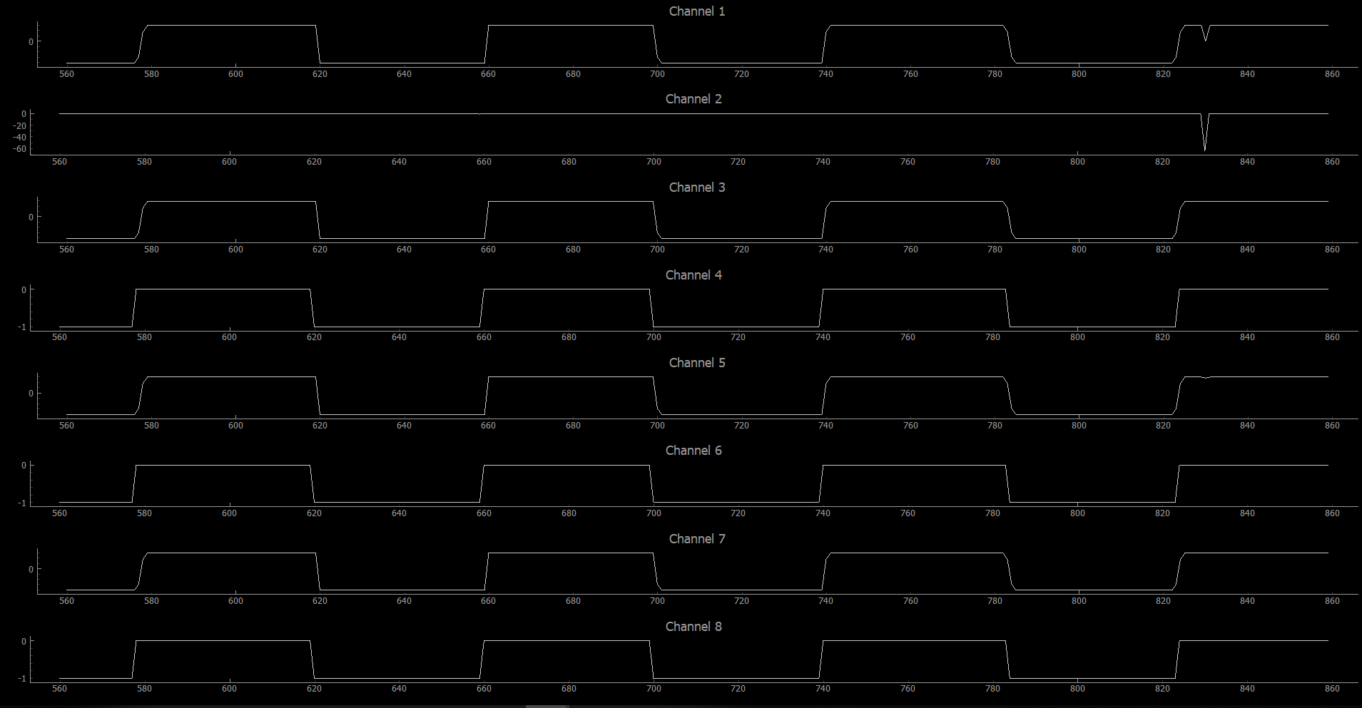
I set the test signals but the amplitud seems weird.

X Axis is the sample number.

Here CONFIG2 is 0xD0

Here CONFIG2 is 0xD1

Here CONFIG2 is 0xD4

Here CONFIG2 is 0xD5

Now I set all the channels in 0xE1 except one channel (0x60 normal input with electrodes) but I get a big sine noise signal just by touching them.

The registers have this configuration:
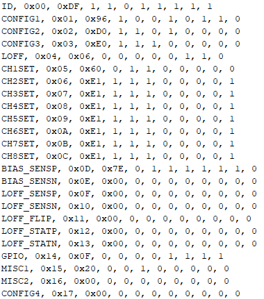
And the output is:

Please help me to solve this.

  • Hell Cristian,

    Welcome to our forum and thank you for your post!

    Let's start with the Device ID...

    For an 8-channel ADS1299, the ID should read XEh, as you said. Typically, an incorrect Device ID is a sign that the device was not initialized properly. After both analog and digital supplies and the VCAP1 voltage have ramped, an extra /RESET pulse is required to ensure the device is in a known good state. There are some internal one-time programmable bits that are read after /RESET is issued and they may be read incorrectly during the initial power-on reset. Please follow the guidelines in Section 11.1 on page 70.

    Regarding the sine wave noise, this is likely from power line noise (i.e. 50 Hz or 60 Hz) coupling onto your body from ambient light sources. Common-mode rejection plays a big role in suppressing this noise. Please review some of the material we have for ECG applications on Right-Leg Drive techniques.

    http://www.ti.com/lit/an/sbaa188/sbaa188.pdf

    Best Regards,

  • Hi Ryan, thanks for replying.

    About the sine wave noise, this time I set channel 1 as BIAS_DRN and connect the SRB1, these two electrodes as reference connected to my body. Measure normal input with channel 2, all the channels left are shutdown and in short. I set the ADS1299 as follows:

    Even doing this I get a sine wave. I realized something, notice how channels 3-8 are shutdown and in short but there is some measure in CH 3-4, CH5-8 have some peaks.

    About the power up, I'm using bipolar supplies, VCAP1 is 1.2V. I read section 11.1 on page 70. My arduino code in the setup function has a 1 sec delay, then reset, stop dataC and read registers. I assume this is OK.

    Today I went to the lab to use the oscilloscope to measure the 3.3V source.

    Here's the device power up (reading or writing some registers)

    Here's with the data stream.

    I'm guessing the power supplies are not good? I'm using 3.3V from Arduino board. I tried to use a voltage source with 3.3V but the device is not recognized, reads 0x00 all the registers. What would be wrong?

  • Hello Cristian,

    I suggest that you try using the internal test signal first to verify that you can read data correctly. Please set CH2SET to 05h. You should see a 1-Hz square wave with an amplitude of 11.25 mV (4.5 V / 2400 * 6).

    Are you intending to use the BIAS electrode? Currently, you have the BIAS amplifier powered down. Without proper biasing, you will experience a lot of power line noise in your measurements. This is a common challenge in biopotential applications. Please review the Bias Drive (9.3.2.4.5) and the Typical Applications (10.2) sections of the datasheet for bias amplifier configuration suggestions.


    Best Regards,