This thread has been locked.

If you have a related question, please click the "Ask a related question" button in the top right corner. The newly created question will be automatically linked to this question.

ADS1298: Using ADS1298 and ADS1294R in daisy chain mode. Issues reading data out

Part Number: ADS1298
Other Parts Discussed in Thread: ADS1294R, , ADS1294

Hi,

We are working on a 12-Lead ECG + Resp design using the ADS1298 and ADS1294R parts. We have them connected up in Daisy chain mode, with the Master in the chain being the ADS1298.

ADS1298 is set up as the master clock generator, CLKSEL = 1 and CLK_EN =1

ADS1294R is set up as the slave. CLKSEL=0

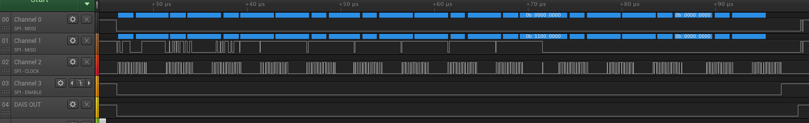
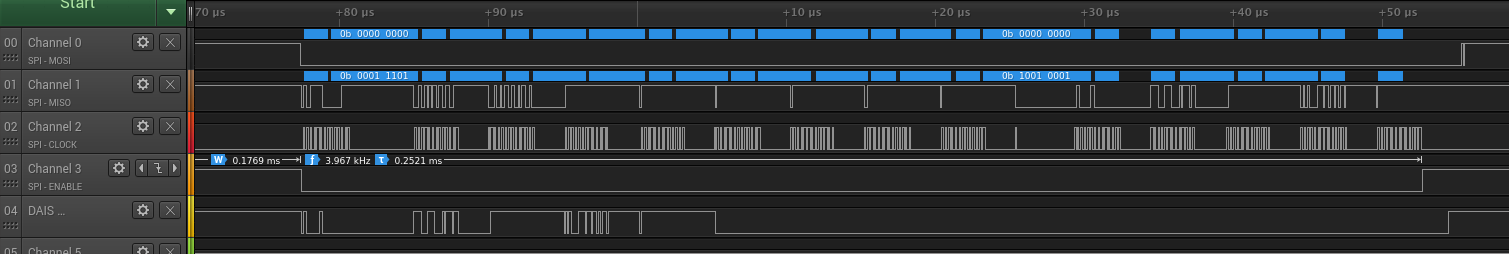
We are trying to use the RDATAC command to read data continuously from both devices. On a Logic analyzer we can see data from the first 8 channels, but in the remaining channels we get no data.

At startup we are setting the config registers to enable the respiration functions, but we are seeing no modulation clock coming from the ADS1294. 

We are using the START Opcode to start conversion and synchronise the devices.

If we set !DAISY_EN! high we can read from both devices, and the modulation clock start operating, which I do not understand since multi-readback is not the correct mode to be in.

Is there something we are doing wrong? Is RDATAC supposed to work in Daisy-Chain mode? What is the correct state for !DAISY_EN!

Thanks for your support,

Dylan

  • Hi Dylan,

    Thanks for your post and welcome to the forum!

    Are you pulling /CS low on the slave device?
    For daisy-chain operation, /DAISY_EN (CONFIG1[6]) must be set to 0. You can write this value to both devices. The last device in the daisy-chain must have the DAISY_IN pin tied to ground.

    These threads may help:
    e2e.ti.com/.../665600
    e2e.ti.com/.../611270
    e2e.ti.com/.../612447
    e2e.ti.com/.../456679
    e2e.ti.com/.../2462806
  • Hi Alex,

    Both devices have /CS tied together and both are driven Low during R/W. 

    One thing we have missed out, is tying DAISY_IN to GND on the final device. On our current prototype DAISY_IN has been left floating. Can you elaborate the impact that this might cause? 

    When we have /DAISY_EN set to 0 we cannot seem able to program the Modulator enable bits on the slave device. At the very least we would've expected to be able to enable the modulator even if we cannot readback from the device.

    Does failing to tie DAISY_IN to GND completely block us from interacting with the device this way?

    Dylan

  • Something else is causing the issue then. DAINY_IN being tied to ground is best practice so that all zeros can be passed (instead of noise) as data if there is an issue, it doesn't explain not getting any data like what you are seeing.

    Can you provide a schematic and register settings?
    Is Daisy of the master tied to DOUT of the slave?
    Do you see /DRDY coming out of both devices and are they synchronized?
    Do you see the same reference voltage on both devices?
    How many SCLKS are being sent to the master device? Is the dead bit between device data being accounted for?
  • Hi Alex,

    Alexander Smith said:
    Something else is causing the issue then. DAINY_IN being tied to ground is best practice so that all zeros can be passed (instead of noise) as data if there is an issue, it doesn't explain not getting any data like what you are seeing.

    I thought this might be the case. Hopefully this means we're dealing with a SW issue then.

    I cannot provide schematics but here is our register table.

    Alexander Smith said:
    Do you see /DRDY coming out of both devices and are they synchronized?
    Do you see the same reference voltage on both devices?
    How many SCLKS are being sent to the master device? Is the dead bit between device data being accounted for?

    /DRDY is only connected to ADS1298, it is not used in our design as both devices are synchronised with START (or should be)

    We can measure a reference at the ADS1298 but can measure no potential difference between the VREFP VREFN pins of the ADS1294. (This seems concerning)

    We are accounting for the dead bit. Here is a logic analyzer trace of the SPI lines. We can see there is no data on the bus for the last device for the final clocking.

    I have attached all of these files, including zoomed plots as a zip.

    Thanks again for the help.

    ADS debug images (2).zip

  • Hi Dylan,

    If you cannot share schematics since this is a forum, I understand. If you like, I can send you an email at your registered email address so that we can continue to discuss offline.

    No potential difference between VREFP and VREFN on the ADS1294 is very concerning. To ensure that the device is receiving power, please probe the power supply (AVDD + AVSS) and GND pins. If the device is receiving power correctly, check if the device is powering up internally by probing the VCAP pins. The VCAP pin voltages for a correctly functioning device can be seen below.
    VCAP1: AVSS + 1.2V
    VCAP2: (AVDD+AVSS)/2
    VCAP3: AVDD + 1.9V

    At first glance, the registers look fine. I'll revisit this if necessary.
    Is it possible for you to check for the ADS1294 /DRDY signal using an oscilloscope? If applicable, is it synchronized to the ADS1298 /DRDY?
    Are you seeing this issue on multiple boards or just one?
  • Hi Alex,

    Dropping me an email could be helpful, I'd appreciate it.

    We've measured the voltages at the VCAP pins and cannot see an issue here. We're confident the devices are both getting power.

    AVDD=2.5V
    AVSS=-2.5V

    VCAP1=1.19 above AVSS
    VCAP2=2.5V above AVSS (So 0V with respect to GND.)
    VCAP3=Reading 4.38V above GND.

    Dylan
  • Hi Alex,

    My initial response is still in moderation but I had another question. Does the state of the internal reference depend on CLK_SEL at all? I can't figure out why the internal supplies are reading OK except the reference.

    Here are some more plots of our SPI transfers. You can see that DAISY_IN in quiet for the entire transfer.

    However, around every 16 transfer cycles we get a small burst of data that probably is noise or something but it does get carried through to DOUT through the ADS1298.

    Thank,

    Dylan

  • Sent you an email!