Hello There,
I've been working with the ADS1299 for some months, and I'm on the stage of testing the Internal Signal of the Device.
I'm working with a Master-Slave architecture where I'm using an evaluation board for ARM Cortex M4 Chip as a Master Device and the Daughter Board of ADS1299 as the slave. Here is a block diagram just to put you in context.
The problem comes when I'm plotting the data, the square wave is getting somehow 'corrupted' and I can see some "steps" at some points, I've been struggling with this for more than a week and I'm wondering if you have an idea of what can be happening. The plotted data looks like this. I just want to clarify that the amplitude is not the right one and we can ignore that for now. Also, I've notice that if I increase the Output Data Rate, the same problem happens, but takes more samples for the problem to appear, so I suppose the issue is somehow related with the output data rate.
The SPI communication is working, I can read all the Registers and I can read back the data. I'm using the device in RDATA mode. Handling the DRDY with an Interrupt and an output data rate of 250 SPS. Then saving this data in a buffer, and when 250 samples are stored, triggering another interrupt for sending the data via UART to USB converter to the computer.
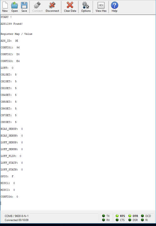
These are my complete register Settings shown in the COM Terminal.
With an Oscilloscope I can see the STATUS data followed by the other Chanel's going positive and negative, so I assume is not a problem of converting the data to Two's complement.
I hope you can help me out with this. If you need any additional information I´m Happy to supply it.
Thanks in advance.
Best regards,
Moisés.


