This thread has been locked.

If you have a related question, please click the "Ask a related question" button in the top right corner. The newly created question will be automatically linked to this question.

AFE5851: Could AFE5851 Sample DC analog input with DC coupling

Part Number: AFE5851

Hi, 

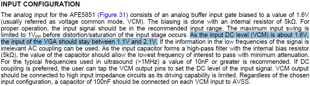
I have an image application that needs 32 analog inputs. I designed it with two AFE5851 chips. The analog input is driven by an amplifier output with 50 OHM serial resistor directly. The amplifier output is 1.1VDC  plus 0 ~ 1V AC signal. 

My question is: If all the 32 channels are with 1.5VDC input, could the AFE5851 provide the correct digital readings?

Best,

Xiuyan

  • Hi Xiuyan,
    How are you?
    Thanks for using AFE5851.
    We will look into it and will reply to you soon.

    Thank you!
    Best regards,
    Chen
  • Hi Xiuyan,

    How are you?

    Thanks for using AFE5851 device.

    According to the AFE5851 data sheet,

    the input signal range should be between 1.1V to 2.1V.

    Because the VCM is around 1.6V.

    If your amplifier output cannot operate within this range,

    we recommend please add a serial capacitor at the input pin (for example, Ch1 Input)

    shown on the following picture from the data sheet.


    Thank you very much!

    Best regards,

    Chen

  • Thanks for the reply, Kung. For our application, the AC coupling for analog input does not work well. Our signal range does vary from 1.1V to 2.1V by considering the driven by 50 OHM and the AFE internally driven by 5K OHM.
    From the Figure 31 you mentioned, the Two Switches indicated "AC coupling" should be ON in order to sample DC analog input.
    Is this switch configured by the General-Purpose Register 21[0], 33[0] or 7[1]?
    What's the default values of the GPR values? Should I configure all the GPR values after powering up?

    Best,
    Xiuyan
  • Hi Xiuyan,

    How are you?

    The AFE5851 device data sheet suggests

    after the device is powered-up, the internal registers must be Initialized.

    Then we can make sure all the internal registers are confirmed.

    and the default values are all zeros.

    Please take a look from the datasheet:


    Thank you!

    Have a nice day!

    Best regards,

    Chen

  • Thank you very much, Chen Kung.
    I think I am all set now. You have a nice weekend!
    Xiuyan
  • Hi Xiuyan,

    Thank you for using AFE5851 device.

    If you are going to choose to use VCA AC coupling (shown above on Figure 31),

    you can see the signal response plot from the data sheet shown as:

    In this case, you can also enable "Highpass Filter (set K=2)" for example.

    Then you can see the final frequency response of the Gain shown as below:

    Thanks and best regards,

    Chen