Because of the holidays, TI E2E™ design support forum responses will be delayed from Dec. 25 through Jan. 2. Thank you for your patience.

This thread has been locked.

If you have a related question, please click the "Ask a related question" button in the top right corner. The newly created question will be automatically linked to this question.

ADS8320: charge bucket configuration

Part Number: ADS8320

Hello,

I'm currently using the ADS8320 in one of my designs. However, I have a question about the configuration of the external RC filter.
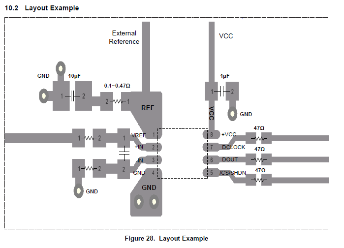
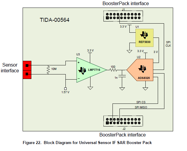
Does this have to be a differential filter, like  stated in the layout example as the first figure. Or should this rather be a single ended version with -In connected straight to GND sense, e.g. second picture?

Thanks in advance,

Sven

  • Hi,

    Sorry, I see that the pictures are not displaying, so here they are

  • Hi Sven,

    A single-ended input charge-bucket filter will be fine as shown in the TIDA.  If you're using the IN- pin of the ADS8320 to sense a remote signal/GND then the additional filter before IN- will help reduce common-mode noise coming from the remote signal/GND.

  • Hi Collin,

    Thanks for the fast response! Do you just add the same RC constant at IN-, or do you use the fully differential filter from the layout guidelines?
    In case of the fully differential one, how do you dimension this? Take the same values as single ended RC filter and use R/2 or C*2?

    Or is there another way to do this?

    I can imagine the differential architecture only makes sense when the input structure is fully differential? In case of this pseudo differential input stage, how should we deal with this?

    Thanks in advance!

    Sven

  • Sven,

    I recommend using the fully-differential filter from the datasheet layout.  You can use the analog-engineer's calculator to find the proper RC values and op amp bandwidth for this type of configuration with a remote-GND sense.  The cap will remain the same but you'll use R/2 for each resistor.