Because of the holidays, TI E2E™ design support forum responses will be delayed from Dec. 25 through Jan. 2. Thank you for your patience.

This thread has been locked.

If you have a related question, please click the "Ask a related question" button in the top right corner. The newly created question will be automatically linked to this question.

DAC161P997: DAC161P997 Output Problem

Part Number: DAC161P997
Other Parts Discussed in Thread: TIDA-00648, DAC161S997, MSP430F5172, XTR115

Hello,

I cant set the Iout of DAC lower then 5mA or higher then 16mA.

const Timer_A_ContinuousModeConfig Fast_Mode =
{
        TIMER_A_CLOCKSOURCE_SMCLK,           // ACLK Clock Source
        TIMER_A_CLOCKSOURCE_DIVIDER_48,      // ACLK/1 = 32.768khz
        TIMER_A_TAIE_INTERRUPT_ENABLE,      // Enable Overflow ISR
        TIMER_A_DO_CLEAR                    // Clear Counter
};

int main(){

MAP_Timer_A_configureContinuousMode(TIMER_A0_BASE, &Fast_Mode);
MAP_Interrupt_enableSleepOnIsrExit();
MAP_Interrupt_enableInterrupt(INT_TA0_N);
MAP_Timer_A_startCounter(TIMER_A0_BASE, TIMER_A_CONTINUOUS_MODE);
Setup_DAC161  (DAC161_STD_ERR_CONFIG_MASKED, 0, 21800);
    while (1)
    {
      MAP_PCM_gotoLPM0();
    }
}

void TA0_N_IRQHandler(void){

MAP_Timer_A_clearInterruptFlag(TIMER_A0_BASE);

DAC161_Set_Out_Value((int)(x * 2730));
      dacStatus = DAC161_Read_Status();
      DAC161_Nop();
}

  • Hi,

    I do not see the code for the DAC161_Set_Out_Value() function, could you share it?

    In addition, can you share an oscilloscope or logic analyzer capture of the write the command?
  • I took the codes from TIDA-00648. then edit it for msp432p401R. I will check with logic analyzer and let you know.

    void DAC161_Write_Regs (unsigned short *writeValues, unsigned char startReg, unsigned char lengthBytes)
    {
        unsigned char outData[3];

        outData[0] = DAC161_SPI_WRITE_CMD(startReg);

        // Switch Endianess
        outData[1] = *writeValues >> 8;
        outData[2] = *writeValues & 0xff;

        USCIB0_SPI_write (outData, RcvData, lengthBytes+1);    // Add 1 to length for command byte

    }

    void Setup_DAC161 (unsigned short errConfig, unsigned short errLow_uA, unsigned short errHigh_uA)
    {
        unsigned short errValue;

        DAC161_Write_Regs (&errConfig, DAC161_ERR_CONFIG_REG, 2);

        errValue = DAC161_CONVERT_ERR_VALUE(errLow_uA) & 0x7f00;
        DAC161_Write_Regs (&errValue, DAC161_ERR_LOW_REG, 2);

        errValue = DAC161_CONVERT_ERR_VALUE(errHigh_uA) & 0xff00;
        if (errValue < 0x80)
            errValue = 0x80;
        DAC161_Write_Regs (&errValue, DAC161_ERR_HIGH_REG, 2);

    }

    void DAC161_Set_Out_Value (unsigned short value)
    {
        DAC161_Write_Regs (&value, DAC161_DACCODE_REG, 2);
    }

    void USCIB0_setupMasterSPI(void)
    {

        DAC_USCIB0_PORTDIR |= (USCIB0_SIMO + USCIB0_SOMI+ USCIB0_CLK);
        DAC_USCIB0_PORTSEL |= (USCIB0_SIMO + USCIB0_SOMI+ USCIB0_CLK);             // Assign SPI pins to Primary Peripheral of USCI_B0
        DAC_CS_PORTOUT |= DAC_CS_N;
        DAC_CS_PORTDIR |= DAC_CS_N;

        EUSCI_B0->CTLW0 |= EUSCI_B_CTLW0_SWRST;                                                       // Enable SW reset
        EUSCI_B0->CTLW0 |= (EUSCI_B_CTLW0_SWRST + EUSCI_B_CTLW0_MST + EUSCI_B_CTLW0_MSB + EUSCI_B_CTLW0_SYNC + EUSCI_B_CTLW0_CKPH );     // SPI Master, 3 wire, synchronous mode
            EUSCI_B0->CTLW0 |= EUSCI_B_CTLW0_SSEL__SMCLK; // SMCLK
            EUSCI_B0->BRW = 8;
        EUSCI_B0->CTLW0 &= ~EUSCI_B_CTLW0_SWRST;                                              // Clear SW reset, resume operation
    }

    void USCIB0_SPI_write (unsigned char *outData, unsigned char *inData, unsigned char length)
    {
        unsigned char i;

            // CS Active Low
            DAC_CS_PORTOUT &= ~DAC_CS_N;
            //__delay_cycles(100);                     // Pause a bit

            for (i=0; i<length; i++)
            {
                inData[i] = USCIB0_SPI_writeByte (outData[i]);
            }
            while (!(EUSCI_B0->IFG & EUSCI_B_IFG_TXIFG));               // USCI_B0 TX buffer ready?
            //__delay_cycles(100);                      // Pause a bit
            DAC_CS_PORTOUT |= DAC_CS_N;

    }

    unsigned char USCIB0_SPI_writeByte (unsigned char data)
    {
            while (!(EUSCI_B0->IFG & EUSCI_B_IFG_TXIFG));                  // USCI_B0 TX buffer ready?
            EUSCI_B0->IFG &= ~EUSCI_B_IFG_RXIFG;                          // Clear RX Interrupt flag

            EUSCI_B0->TXBUF = data;                             // Place data in TX Buffer
            while (!(EUSCI_B0->IFG & EUSCI_B_IFG_RXIFG));                 // Wait for end of data receive
            return ((unsigned char)EUSCI_B0->RXBUF);
    }

  • Hello,

    As Paul mentioned before I think the best way to start debugging this is to take a look at the SPI waveforms. Can you provide SCLK, SDO, and CS on one capture when you update the DAC?

    Thanks,
    Garrett
  • as you can see at the code i readm error status so if there is an error i clear it but i think it keeps giving an error continously sooutput cant goes that high or low. Lets say i decided to get 2mA as output. at multimeter i can see the value which i decided but it changes all the time like 2ma 10ms after 5ma then again 2ma then again 5ma....
  • i put Setup_DAC161 (DAC161_STD_ERR_CONFIG_MASKED, 0, 21800); after DAC161_Set_Out_Value and problem solved. Is it OK ? it is weird
  • Hello,

    I would not expect this to resolve the problem. Setting the ERR_LOW_REG to 0 is not valid and will retain the previous value. Is the output stable at the correct value now? In the previous case can you monitor the ERRB pin to see if an error is occurring that would cause the current output to go to one of the error levels?

    Thanks,
    Garrett
  • OK. I have two boards with DAC161S997. One of them has its own MCU(msp432p401R) other one is just for DAC and connects to msp-exp432p4111 with jumpers. Codes are the same. Designs are the same but the one with the MCU still cant set the output less then 5.5mA. But it can be 20mA perfectly. using Setup_DAC161  (DAC161_STD_ERR_CONFIG_MASKED, 3375, 21750); as you said 0 is not valid.

  • Hello,

    The software for TIDA-00648 was written for MSP430F5172. I am not sure if it is compatible with the devices you have tried without some modifications as these are pretty different architectures overall.

    Thanks,
    Garrett
  • i did lots of modifications. As i said it works. please just check my codes at 3rd comment of this topic
  • Hello,

    Glad you were able to get it working. As long as the DAC is producing the correct value after the SPI write the code should be okay.

    Thanks,
    Garrett
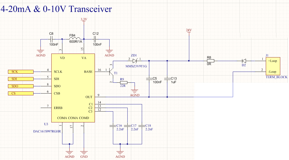
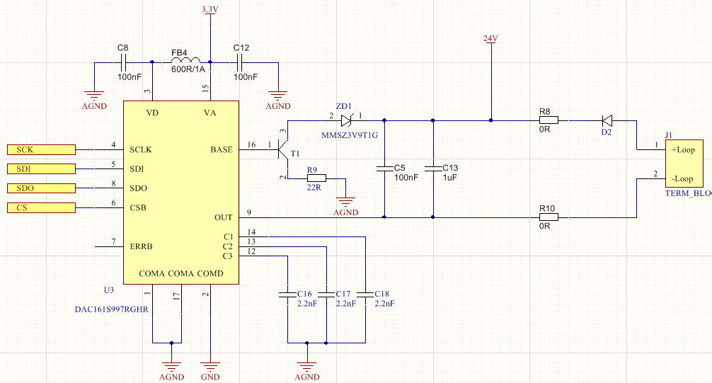
  • i think this dac has some problems. probably i broke 5 of them. and i have no idea what is damaging it.Something happens and it stop working and i see 20v at outputs of dc/dc conterters of mine. Is there any must for measuring output ? I probably gonna use an other voltage DAC and xtr115 with it. but thank you for your help.
  • Hello,

    I have not seen issues where the DAC is damaged before. One possibility is that the voltage on the device pins is exceeding the absolute maximum rating. Which voltage do you see going to 20V, the loop supply voltage? How are you connecting the loop supply and load?

    Thanks,
    Garrett
  • i connect multimeter's one probe to the -loop and other one is to AGND. Yes of course it will be damaged if its pins exceed the absolute max rating. But it is the one which does that. if i change it with new one. Everything works fine until it is broken again. I have a converter which converts 24V(loop+) to 5v and a LDO which converts 5V to 3.3V. something happens and everyhing stops working. and i see 20V at these converters' outputs. As i said if i change DAC with new one. Everything is OK. and yes oddly nothing gets damage because of this!

  • I am going to close this and create a new one.