This thread has been locked.

If you have a related question, please click the "Ask a related question" button in the top right corner. The newly created question will be automatically linked to this question.

ADS1115: Problem when working in single shot mode using 'alert/rdy' pin and input is connected to ground or not connected.

Part Number: ADS1115

Hi

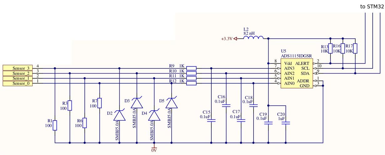
I'm developing my own device which uses ADS1115. I'm using connection as in the picture below. I configure ADS1115 as follows:

adcInitConf.compQue = COMP_QUE_ONE;
adcInitConf.compLat = COMP_LAT_ENABLE;
adcInitConf.compPol =  COMP_POL_HIGH;
adcInitConf.compMode =  COMP_MODE_WITH_HYSTERESIS;
adcInitConf.dr = DR_128_SPS;
adcInitConf.mode = MODE_SINGLE_SHOT;
adcInitConf.pga = PGA_6_1;
adcInitConf.mux = MUX_0_G;
adcInitConf.osWrite = OS_WRITE_BEGIN;

I'm waiting for 'alert/rdy' pin is high and read value from ADC. It works is well but if ADS1115 input is not connected or connected to ground ADC don't set 'alert/rdy' pin. In this case, I expect to get a zero value.

Any ideas?  Is any additional information required?

Thanks very much,

  • Artem,


    Out of curiosity, what do you have the Hi_thresh register and Lo_thresh register set to? The conversion-ready function of the ALERT/RDY pin is enabled by setting the Hi_thresh register MSB to 1 and the Lo_thresh register MSB to 0 (MS bits). This is similar to the comparator mode, except that in this case, every conversion triggers the alert. Also, COMP_QUE should be set to 00 to assert after one conversion (right now you have it listed as COMP_QUE_ONE, which may be correct).

    If that doesn't pan out, what output data are you getting from the ADC without inputs connected and you just do a normal reading? With the R1, R3, R6, and R7, you should be pulling the inputs to ground and you should just read 0000h.


    Joseph Wu
  • Joseph Wu,

    Do I need to set to Hi_thresh register: 1111 1111 1111 1111, and to Lo_thresh register: 0000 0000 0000 0000?
  • Artem,


    That is correct. This would set the Hi_thresh register to -1 and the Lo_thresh register to 0. This basically forces the ALERT/RDY flag to trip on each conversion. Test this and let me know that it worked.


    Joseph Wu
  • Joseph Wu,

    To my regret, it doesn't work. ALERT/DRY always in low state. If I ignore it and continue to read the conversion register readings are true but the ALERT / RDY pin is not set.

    Thanks, Artem
  • For example.

    I do initialization ADS1115:

    BOOL ADS1115_Init(struct __I2C_HandleTypeDef *pIntfc) {
    struct ADS1115_Config adcInitConf;
    adcInitConf.compQue = ADS1115_COMP_QUE_ONE;
    adcInitConf.compLat = ADS1115_COMP_LAT_ENABLE;
    adcInitConf.compPol = ADS1115_COMP_POL_LOW;
    adcInitConf.compMode = ADS1115_COMP_MODE_WITH_HYSTERESIS;
    adcInitConf.dr = ADS1115_DR_128_SPS;
    adcInitConf.mode = ADS1115_MODE_SINGLE_SHOT;
    adcInitConf.pga = ADS1115_PGA_4_1;
    adcInitConf.mux = ADS1115_MUX_0_G;
    adcInitConf.osWrite = ADS1115_OS_WRITE_BEGIN;
    
    uint8_t adcRegData[3];
    ADS1115_MakeConfigData(&adcInitConf, adcRegData);
    
    // Writing configuration data to ADS1115
    if(HAL_I2C_Master_Transmit(pIntfc, ADS1115_ADR << 1, adcRegData, 3, ADS1115_TIMEOUT_TRANSMIT) != HAL_OK) {
    return FALSE;
    }
    
    // Writing 0x0000 to Lo register ADS1115
    adcRegData[0] = ADS1115_REG_ADDR_LO_THR; // 2
    adcRegData[1] = (uint8_t)(0x00);
    adcRegData[2] = (uint8_t)(0x00);
    if(HAL_I2C_Master_Transmit(pIntfc, ADS1115_ADR << 1, adcRegData, 3, ADS1115_TIMEOUT_TRANSMIT) != HAL_OK) {
    return FALSE;
    }
    
    // Writing 0xFFFF to Hi register ADS1115
    adcRegData[0] = ADS1115_REG_ADDR_HI_THR; // 3
    adcRegData[1] = (uint8_t)(0xFF);
    adcRegData[2] = (uint8_t)(0xFF);
    if(HAL_I2C_Master_Transmit(pIntfc, ADS1115_ADR << 1, adcRegData, 3, ADS1115_TIMEOUT_TRANSMIT) != HAL_OK) {
    return FALSE;
    }
    
    return TRUE;
    }


    And then I read value use for example same function:

    BOOL ADS1115_ReadInput(struct __I2C_HandleTypeDef *pIntfc, const uint8_t *pConfigRegister, uint16_t *inputValue) {
    // Say to make a measurement
    if(HAL_I2C_Master_Transmit(pIntfc, ADS1115_ADR << 1, pConfigRegister, 3, ADS1115_TIMEOUT_TRANSMIT) != HAL_OK) {
    return FALSE;
    }
    
    uint32_t tickstart = HAL_GetTick();
    // Wait until ADC has done measure
    while(HAL_GPIO_ReadPin(ADC_Alert_GPIO_Port, ADC_Alert_Pin) != GPIO_PIN_RESET) {
    if ((HAL_GetTick() - tickstart) > ADS1115_TIMEOUT_TRANSMIT) {
    return FALSE;
    }
    }
    
    // Reading data from ADC
    uint8_t reciveData[2];
    uint8_t addrConvReg = ADS1115_REG_ADDR_CONV;
    if(HAL_I2C_Master_Transmit(pIntfc, ADS1115_ADR << 1, &addrConvReg, 1, ADS1115_TIMEOUT_TRANSMIT) != HAL_OK) {
    return FALSE;
    }
    if(HAL_I2C_Master_Receive(pIntfc, ADS1115_ADR << 1, reciveData, 2, ADS1115_TIMEOUT_TRANSMIT) != HAL_OK) {
    return FALSE;
    }
    
    // Put data to inputValue
    *inputValue = (reciveData[0] << 8);
    *inputValue |= (reciveData[1]);
    
    return TRUE;
    }

  • Artem,


    I don't see anything wrong in the code, but there are two things that I would like to try.

    First set the Hi_thresh register to 8000h and set the Lo_thresh register to 7FFF. This would completely invert the high and low threshold registers.

    Second, I would get a scope plot or logic analyzer and put up plots of the I2C transactions for programming in the configuration register, the hi-thresh register and the low_thresh register. Then get plots for reading back the same 3 registers as well. I'd look at SDA, SCL, and the ALERT/RDY pin as well. I just want to verify that the communication timing and the values are correct.

    There is one thing that I didn't understand earlier. You said that the ready pin worked when you have the inputs plugged in and measuring something, but it didn't work when the inputs were floating or connected to ground. In your setup, with the 100 Ohm resistors at the inputs, you really don't have a floating case. How large is the input, have you tried measurements where the inputs were made smaller and smaller? Is there anything different in the grounding with the device, microprocessor, or input signal?


    Joseph Wu
  • Joseph Wu,


    At the first case i have set the Hi_thresh reg to 0x01 and the Lo Thresh reg to 0x00. And it works well when I use potentiometer, but when I connect input to GND or not connect it doesn't work. Note: I want to measure between sensor and ground.


    Thanks, Artem
  • Joseph Wu,

    I set the Hi_thresh register to 8000h and set the Lo_thresh register to 7FFF and it doesn't works.

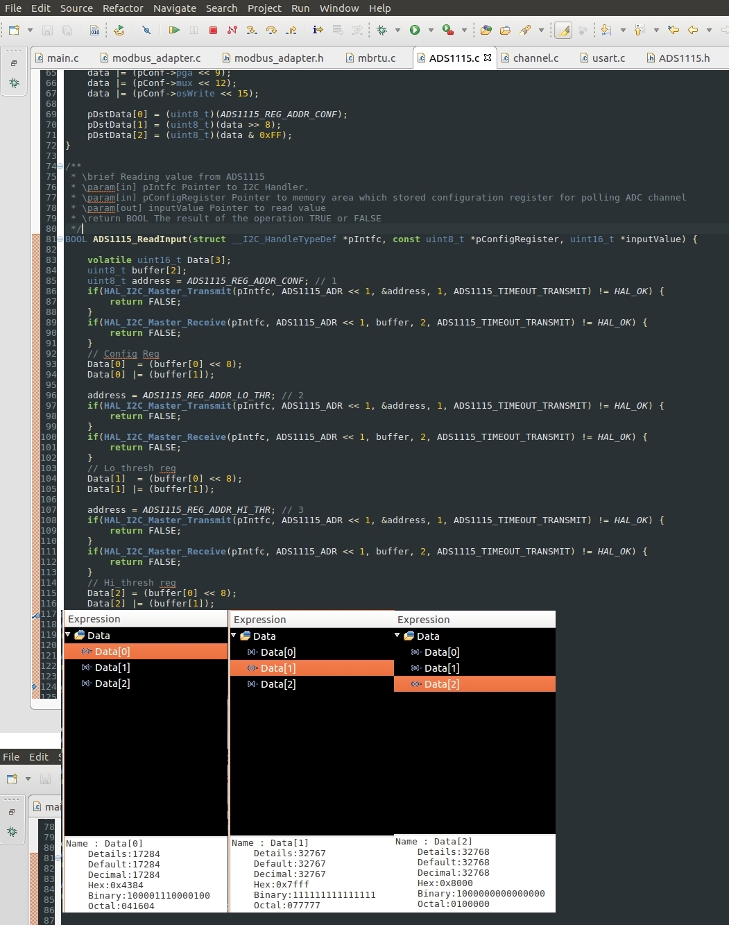
    On the first screen: I read the values of the registers from the ADS1115.

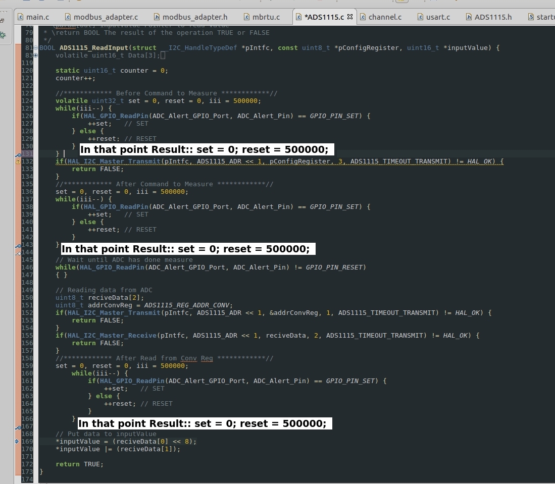
    On the second screen: I showed that the ALERT/RDY Pin is always low. I think it should be like this: at the first point: set = 500000; reset = 0; at the second point: set = 3100(8ms), reset = 496900; at the third point: set = 500000; reset = 0;

    Thanks

    Artem

  • Artem,


    I'm sorry I didn't get back to this thread earlier. Were you able to debug this problem? In looking at your posts, I think this is still an error in programming the threshold values. If you get it to work with the sensor in place, but it stops working when the inputs are shorted or floating, it seems that the only difference would be the ADC output value.

    In my previous post, I asked for the scope shots of the communication. I still think that's important. I'd like to see the threshold values programmed in. I would still use the Hi_thresh register set to 8000h and set the Lo_thresh register set to 7FFF.

    Other than that, I would first get the RDY pin working and start making smaller changes to debug this problem. Set the device in continuous conversion mode to see the RDY indication, or setting the device to non-latching to see if the RDY returns on it's own.


    Joseph Wu
  • Joseph Wu,

    In my last post I read registers Config, Lo_thresh and Hi_thresh. As you can see I use the parameters as you advised. 

    The Hi_thresh(Data[2]) = 0x8000;

    The Lo_thresh(Data[1])=0x7fff;

    The Config(Data[0])=0x4384;

    In this case in the Config register(0x4384) I have:

    Parameter

    Current value (Binary)

    Meaning

    COMP_QUE

    00

    Assert after one conversion

    COMP_LAT

    1

    Non-latching comparator

    COMP_POL

    0

    Active low

    COMP_MODE

    0

    Traditional comparator with hysteresis

    DR

    100

    128SPS

    MODE

    1

    Power-down single-shot mode

    PGA

    001

    FS = ±4.096V

    MUX

    100

    AIN P = AIN0 and AIN N = GND

    OS

    0

    Device is currently performing a conversion

    Thanks

    Artem

  • Artem,


    COMP_LAT=1 is actually the latching comparator (not the non-latching comparator as mentioned in your table). As I mentioned in one of my previous posts, I would have used the non-latching one, so the configurations should be 4380h.

    If you continue to have a problem, the reason for checking the scope shots is to see that the data correctly programs the device into the correct registers. I still think that's important.

    Again, I find it suspicious that the problem occurs with the inputs floating or grounded. This still leads me to incorrectly programmed threshold values. I would still use Hi_thresh = 8000 and Lo_thresh = 7FFF. Just make sure that the registers are correctly programmed by verifying the register pointer value and the registers programmed value.

    Also, to try to debug the problem, I'd still get RDY working as you had before, check to see if it works in continuous conversion mode, and then check to see if there are problems with different input values.


    Joseph Wu
  • Joseph Wu,

    Now, I have such a situation: state the ALERT/RDY Pin always is LOW, when I send the command to 'start measure' the ALERT/RDY Pin change state to HIGH on 8 ms and then it change to LOW even after  reading  measured value. I think after reading  measured value ALERT/RDY Pin has to change state (to reset) to HIGH. Why isn't it working?

    Thanks very much, Artem

  • Artem,


    The ALERT/RDY state doesn't change with a read of the device, the ALERT/RDY only goes low at the completion of a conversion.


    Joseph Wu
  • Artem,


    Did you have any further questions on the ADS1115? I'm going to close this thread for now, but if you have other questions, you should be able to come back an add more posts to this thread.


    Joseph Wu