This thread has been locked.

If you have a related question, please click the "Ask a related question" button in the top right corner. The newly created question will be automatically linked to this question.

ADC12DJ3200: Flatness specs

Part Number: ADC12DJ3200
Other Parts Discussed in Thread: TSW14J57EVM

Hi team,

My customer use the ADC12DJ3200 EVM and the TSW14J57EVM to test the flatness.

Below is the setting:

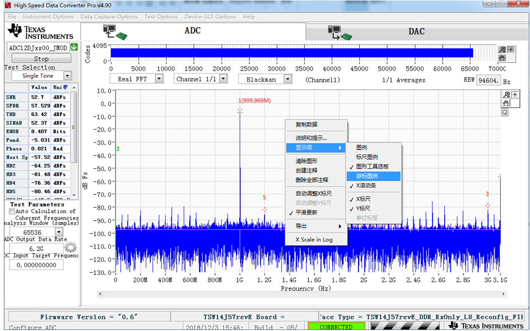
The output data rate is 6.2G.

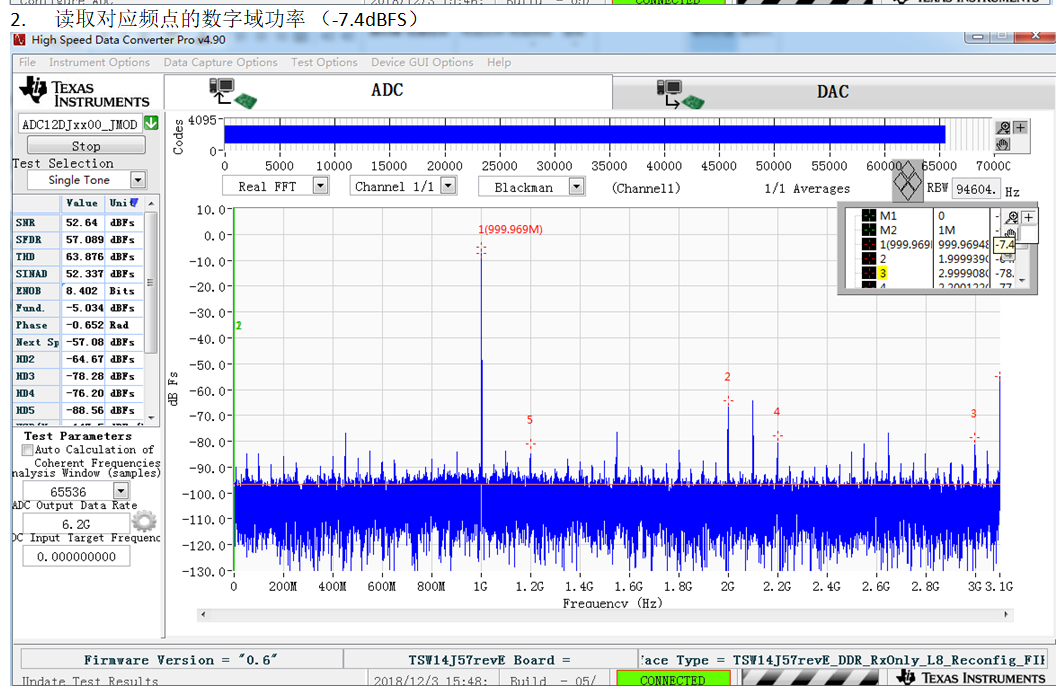
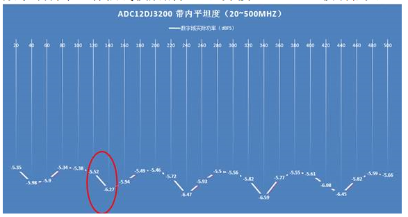
And they input the signal with 20MHz space signal tone from the 20MHz to 500MHz, the amplitude is 0db, and use the cursor to capture the FFT amplitude(see as below)

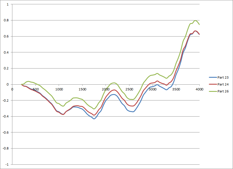
But they find the results show the maximum value between two point is larger than 0.7dB, see below:


Does this spec make sense?

Or if there are some measurement mistaken?

Please help to comment!

Lacey

Thanks a lot!

  • Hi Lacey

    The variation in amplitude response versus frequency on the EVM is primarily due to reflections between the balun output and ADC input ports.

    The balun used on that board has poor output return loss. This combined with the input return loss of the ADC causes reflected energy between the balun outputs and ADC inputs to give a cyclical gain response versus frequency.

    The amount of variation seen in your own design can be reduced by any of the following changes:

    • Place the balun as close as possible to the ADC inputs (this will also make the ripple versus frequency have a smaller frequency delta between peaks or dips)
    • Add a resistive attenuator between the balun and ADC inputs
    • Select a different balun with improved output return loss

    There may also be some reflection between the signal generator output and the input of the EVM. Adding an RF attenuator at the input to the EVM would help in this case.

    I hope this is helpful.

    Best regards,

    Jim B

  • Hi Jim,
    Thanks so much for your reply!
    So for the flatness specs, customer's requirement is 0.2 to 0.3dB with the 20MHz step from the 20MHz to 2800MHz.
    Can the ADC12DJ3200 meet this requirement?
    Lacey
    Thanks a lot!
  • Hi Jim,
    Can you also help to share the data you have tested in the lab?
    Because it's hard for customer to do the change in the EVM as you described above.
    Now customer need the flatness data to evaluate if the device can meet their requirement.
    Lacey
    Thanks a lot!
  • Hi Lacey
    I have requested the data from the team that did the measurements. I'll provide it here as soon as I have it.
    Best regards,
    Jim B
  • Hi Lacey

    Here is a plot of the input gain response data taken on 3 units up to 4 GHz input frequency. Negative values are more attenuation, positive values are less attenuation. Some peaking circuitry is included to enhance the response above 3500 MHz, that is why the values increase in that region.

    Best regards,

    Jim B