I'm using the ADS1299EEG-FE to carry out a test on an 8 channel EEG system. The total number of electrodes is 10: 8 channels + 1 reference + 1 patient bias electrode.
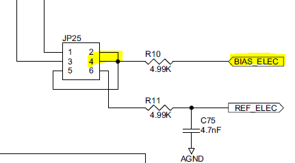
I am connecting the 8 channels to the corresponding pins on J6 [36, 32, 28, 24, 20, 16, 12, 8], and I was under the impression that I could connect the reference electrode to pin [6] on JP 25, apply a jumper to pin 1,2 on J6 to route the reference signal to all the negative inputs through SRB1. I also wanted to connect the patient bias electrode such that it would drive the patient to mid supply voltage, and I am doing so by connected the reference electrode to pin [4] on JP25.
I havn't tested the system yet, because I am not sure about any of the reference or the bias electrode connections, and I have tried reading through the user's guide, but I couldn't clearly understand how the connections should be made. Most of the connections I have currently made are from suggestions on the forum from similar set ups.