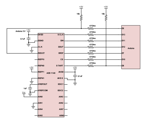
Part Number: ADS1148
Other Parts Discussed in Thread: ADS1120, ADS114S08
I am controlling the chip with an arduino Uno Rev3. The arduino built-in SPI interface did not work for me for some reason; therefore, I'm using bit banging for all spi communications.
The code was based on the pseudocode provided in the datasheet. I have attached the code and the scope captures at the bottom of this post.
- Able to write to the registers and did a sanity check by reading back the registers.
- Pulsed the START pin high to start the conversion
- DRDY pin did go low after start pin pulsed high
- polling for DRDY 0 instead of an interrupt
- DRDY did force high on the first falling clock edge
- sent the RDATA command and 16 clks afterwards to try to clock out the conversion data... however MISO just kept returning 0
- everything seems to be working but I just cannot clock out the result!!
Please provide some assistance. Thanks in advance.
scope captures:
https://www.dropbox.com/s/bj81xcmidpah292/scope%20captures.pdf?dl=0
arduino code:
https://www.dropbox.com/s/et9cm1jrhfwir3u/adc.zip?dl=0