This thread has been locked.

If you have a related question, please click the "Ask a related question" button in the top right corner. The newly created question will be automatically linked to this question.

ADS8638: ADS8638 output error

Part Number: ADS8638
Other Parts Discussed in Thread: ADS8634

Hi All,

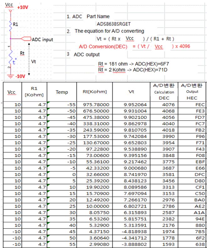
My customer is evaluating ADS8638 to sense the temperature from a thermistor(NTC).

Looking at the output data, HEX value doesn't match with what Samsung calculated(DEC) based on the Rt and Vt.

For example, if Rt is 2kohm, the output should be 4EC but ADC output 71D not 4EC.

Would you let me know how this issue can be solved? I attached the schematic of ADS8638.

Best regards,

Sammy

  • Sammy,


    Because the ADS8634 has so many different possible configurations, it is important to make sure that the settings are properly programmed in. Are the input channels programmed through a manual mode, or through the configuration registers. What is the range select value?

    If they are making single ended measurements, I believe the input are measured from AINx to AINGND. In the customer's schematic. Also, where does the Rt current return go? In the photo of the excel spread sheet, it says -10V. However, I don't see the -10V connection in the schematic.

    Assuming that the device is making measurements, has the customer used a multimeter to measure the input voltage? They should verify that the input voltage is correct as expected from the voltage divider. They've made two measurements with 181Ω and 2kΩ and gotten date. I would use a few more resistance values and make some measurements with a wider range of inputs. Also, I would measure the voltages across R1 and the resistor used for Rt.


    Joseph Wu
  • Sammy,


    It has been some time since your last post, and I was wondering if your customer's problem with the ADS8634 has been resolved. I had mentioned a few things to try in my last post. However for a solution, I think we would need much more information about the mode of operation and the customer's setup.

    I'll close the post for now, but if there are further questions, you should be able to post again to keep the thread open.


    Joseph Wu
  • Hi Wu,

    Thanks for your answer.

    My customer is using auto scan mode for input channels. Below is the register settings that customer has checked.

    They set all channel(CH0~CH7) to be sampled even though all channels are not used. The signal range seems to be selected as +10V referring to customer's register setting.

    BTW, I have one question about how to read the bits in the register.

    Looking at the datasheet, if the Auto-Md Ch-Sel register is programmed to 01100100, then the auto-mode sequence is channels 2,5,6.

    However, I thought that channels 1,2,5 might be selected. 

    • Would you let me know how to read the binary bit for the register? If register value is 02h, is it 00000010? If so, only channel 6 would be chosen for scanning?

    In the schematic, N10V_temp means -10V.

    Regarding the measurement on the input voltage, I didn't receive any answers from customer yet. I will let you know once customer gets back to me.

    < Register values that customer has checked >

    1. After power on reset, page0 register read value

     reg04 : 00
     reg05 : 00
     reg01 : 00
     reg06 : 08
     reg0c : 00
     reg10 : 11
     reg11 : 11
     reg12 : 11
     reg13 : 11


    2. After reading register as above, Write page0 register

     reg0c : ff
     reg05 : 02


    3. After writing to registers(reg0c, reg05), Read page0 register

     reg04 : 00
     reg05 : 02
     reg01 : 00
     reg06 : 08
     reg0c : ff
     reg10 : 11
     reg11 : 11
     reg12 : 11
     reg13 : 11

    Best regards,

    Sammy

  • Sammy,


    I'm sorry I missed this post last week. It does seem like there is an error in the datasheet. I would guess that the register description is correct but the example used in the datasheet is not. I'll need to check with the systems group and see if they have any comment.

    Thank you for the register settings. I'll look through them and maybe I'll have more comment when the customer has more measurement data.


    Joseph Wu
  • Sammy,


    I did hear back from the design team. The bit field descriptions from the table are correct, so the example description does have an error.

    Again, I'll close out the post, but you can open it again if the customer comes back with more data.


    Joseph Wu