This thread has been locked.

If you have a related question, please click the "Ask a related question" button in the top right corner. The newly created question will be automatically linked to this question.

ADS7845: LSB of SPI clocked data is always either 0x78 or 0xF8

Part Number: ADS7845

Touchscreen: FTAS00-10.4A-5 (5-wire)

TS Controller: ADS7845 on the TI ADS7845 Eval Kit

Input Voltage: 3.3V

VREF is N/C to allow for Differential (no jumpers on JMP1)

wiring from Touchscreen to header on Eval Kit triple checked.

Generally, the electrical configuration is working as expected: touch the screen, get an interrupt, MOSI/MISO traffic is functional.

With one exception: for both the X and Y reported data, the LSB is always either 0x78 or 0xF8. And this causes significant mis-reporting of where the touch occurs. Running ts_calibrate helps, but the results are only accurate near the calibration points. I realize that the lower 3 bits should always be 0, bit I would at least expect the upper nibble of the LSB to be more dynamic.

I am using a logic analyzer to watch the MOSI/MISO stream, so at this point the (Linux) driver is not yet in question.

Here is a series of transactions between the CPU and the 7845 when touching the center of the screen:

MOSI / MISO

0x91 / 0x00 - Start/Y/12-bit/Differential/Power Down/IRQ Disabled

0x00 / 0xBA

0x00 / 0xF8

0xD1 / 0x00 - Start/X/12-bit/Differential/Power Down/IRQ Disabled

0x00 / 0xB6

0x00 / 0x78

0x91 / 0x00 - Start/Y/12-bit/Differential/Power Down/IRQ Enabled

0x00 / 0xB7

0x00 / 0xF8

0x91 / 0x00

0x00 / 0xBB

0x00 / 0xF8

0xD1 / 0x00

0x00 / 0xB7

0x00 / 0xF8

0x90 / 0x00

0x00 / 0xB8

0x00 / 0xF8

Thoughts on why this might be occurring and how to rectify it?

  • Hi Kevin,

    Thanks for your post and welcome to the forum!

    Sorry for the delay in response, our primary support for this device is currently traveling. Please give us a few days to take a look at this issue.
  • Kevin,

    Can you please attache a scope waveform for your digital interface (CS, DCLK, DIN, DOUT)? We want to verify your timing.

    Best regards,
  • Here's the capture. Keep in mind that the sample rate for the system and clock aren't consistent; so the clocks varying width isn't an issue.

  • Kevin,

    Below is a list of some comments and questions that may help with the debug.  Let me know if this helps or if you have further questions.

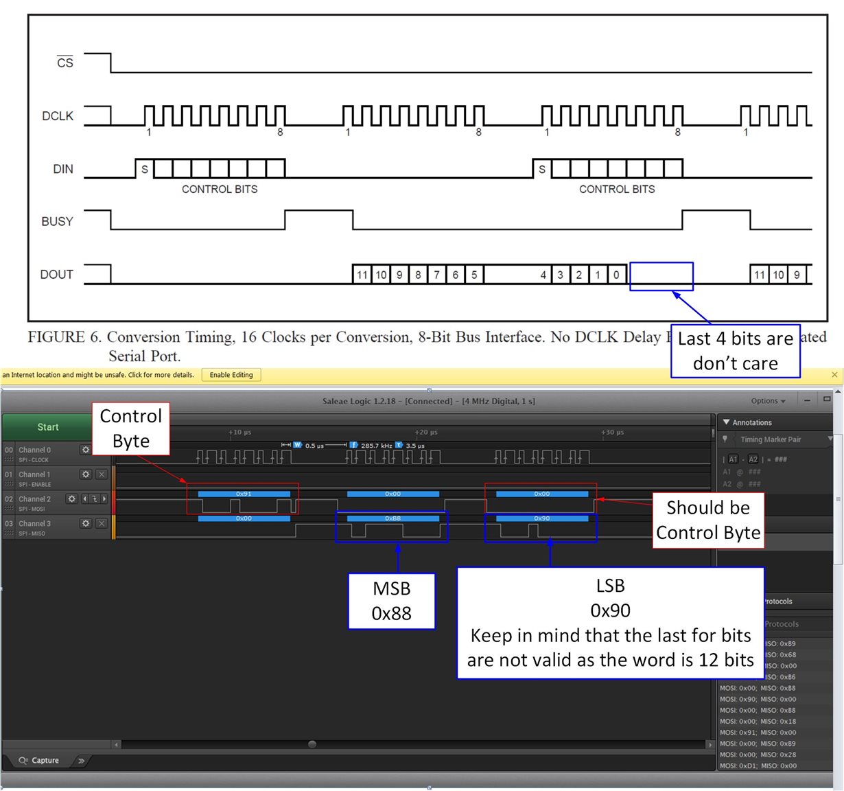
    1. Based on your control bits you are doing a 12 bit conversion. You are doing two 8 bit reads (16 bit total). So the last 4 bits in your reads should always be zero. That looks correct in your sample data.

    2. Every other 8 bit transaction should write to the control bits. You write to the control bits in the first transaction but do not do this for the third transaction. This may be the issue. See figure below comparing the data sheet timing diagram to your measurement.

    3. Your 16 bit read is 0x88 0x90. This corresponds to a 12 bit value of 889H. I’m not sure why you say that the LSB is always 0x78 or 0XF8. Am I missing something?

    4. Can you add Busy to your capture?

  • Art -

    Thanks for the guidance. I'll check it out as soon as I can.

    Just a quick note on #3: Where is the 0xF8 or 0x78 in the LSB? Well, I was doing some more experimentation, and changed the voltage input from 3.3 to 5.0, and was getting different answers back (obviously), but the touchscreen was still not behaving as expected. Not sure why the voltage level change would matter - can you provide insight into that?

    Thanks,

    Kevin

  • Here's some updated info. It seems better, but there are some oddities:

    1) The MS bit is always '1'. Is this expected?

    2) The LSB has started to show the 'F8' and '78' phenomenon again.

    2) As I move along the Y direction, the X value changes as well, but not as much as Y. Same with moving along the X direction, the Y value changes. Yes, I would expect some jitter, but the values clearly increase.

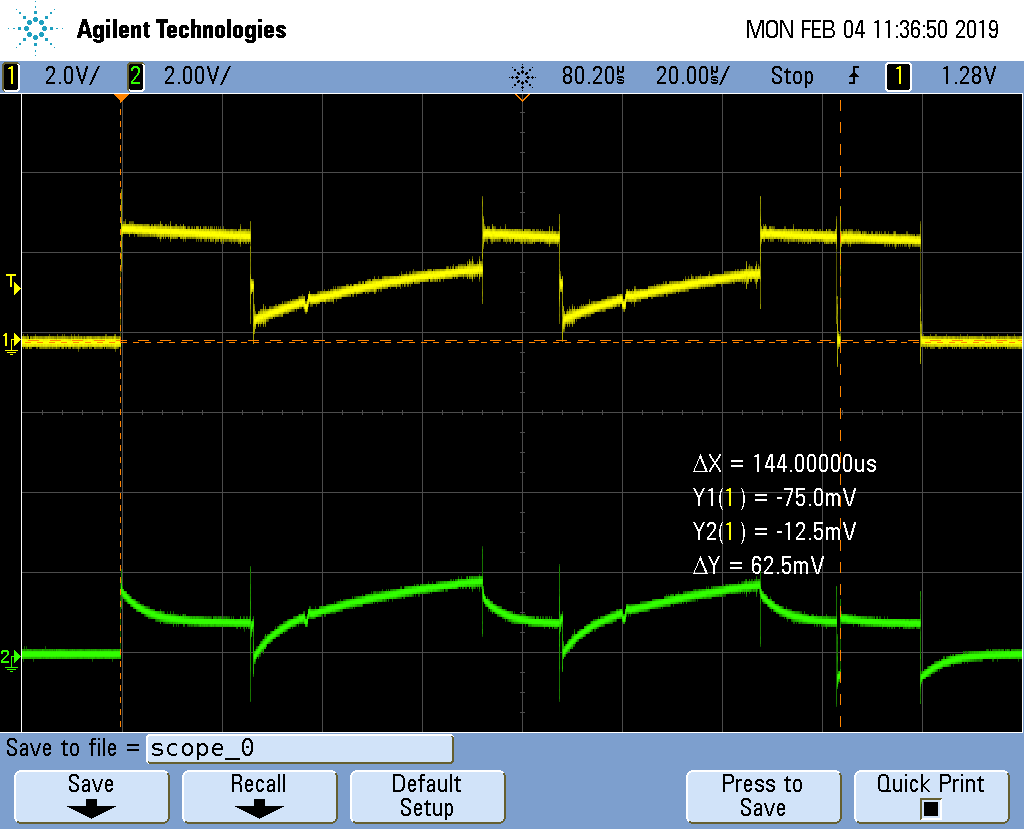
    I've attached the SPI communications, including the busy signal, as requested. And I've also attached LU and Wiper, as there seems to be issues with the voltage signals as well. Channel #2 (green) is the wiper.

  • Got it all worked out:

    1) The touchscreen needed 5.0v not 3.3V that I was supplying (this resolves the 0xF8/0x78 LSB issue)
    2) The MSbit is always one according to the datasheet. I was mis-reading the timing diagram.
    3) I needed to decrease the SPI clock and perform several samples in a row in order for the voltage to settle. We have a prototype setup that may be adding too much capacitance to the analog lines, and hopefully that can be fixed in the final product.

  • Kevin,

    Thanks for sharing your feedback with the community. We're glad it worked out.