This thread has been locked.

If you have a related question, please click the "Ask a related question" button in the top right corner. The newly created question will be automatically linked to this question.

ADS1018: ADS1018

Part Number: ADS1018

Hi,

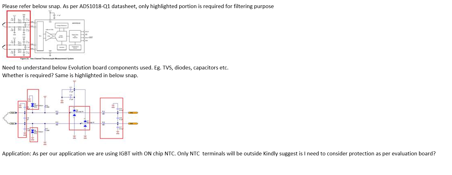
I am using component 

ADS1018 ADC converter IC.

I need to calculate power dissipation of IC.

Temperature consideration is 105dC.

Supply voltage is 5V

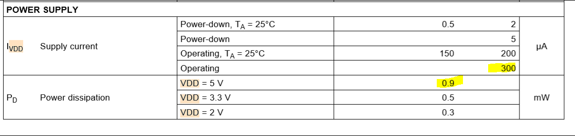
Operating current 300uA max (as per datasheet for )

and allowed power mentioned is 0.9mW (as per datasheet for 5V)

PD = Vcc * Icc

PD = 5 * 300uA

PD = 1.5mW which greater than allowed.

Can you check my calculation and provide me the solution.

Siddharth Sangam

  • Siddharth,


    If you are operating over high temperatures, then you calculation of PD=5*300uA is correct. This would give a max power dissipation of 1.5mA.

    From the datasheet, the supply current is typically 150uA and max 200uA at 3.3V supply and at an ambient temperature of 25°C. The larger 300uA max comes from the operating temperature range going to 125°C. The power dissipation given as 0.9mW is the typical power dissipation, not the max.

    The easiest way to estimate the typical power consumption is to look at the typical characteristic curve for operating current. This can be found in Figure 2 of the ADS1018 datasheet.


    Joseph Wu
  • Hi,
    Joseph

    Need
    V.OH
    V.OL
    V.IH
    V.IL
    Above values for 5V Vcc.As they are not mentioned in datasheet.


    Siddharth Sangam
  • Siddharth,

    The digital voltage levels are described in the electrical characteristics table. Threshold levels scale with the supply voltages. Here's a clip of the specified values on page 7 of the datasheet.

    Joseph Wu

  • Siddharth,


    I don't know if the extra diodes, TVS, and capacitors are necessary in your application. I don't know the environment which your board will be working in, or how often an ESD or over voltage event will occur, or if you're willing to put in extra expense into your board. I can only comment on the devices and how they may affect the circuit.

    Going from left to right in the second circuit, I don't think these capacitors are necessary. There may be some additional filtering benefit from the measurement, but there is already input filtering (both differential and common-mode) at the input of the ADC. For the next part, it looks like you have some TVS diodes at the front end. I've seen them used, but just remember that these may have a large amount of leakage current. If you are measuring a resistive element like an RTD, this may contribute a significant amount of error. After that, it looks like there are some Schottky diodes that latch the ADC inputs to the positive rail and ground, just in case of over voltage events. Again, these may contribute some amount of leakage. In both cases for leakage current you also need to consider if they react with the input series resistance used in the filtering.

    As for the last differential and common-mode filtering, I think this is generally necessary. We recommend using this filtering and setting the differential bandwidth about 10x the data rate. Then select common-mode capacitors to be about 10x smaller than the differential capacitors.


    Joseph Wu