This thread has been locked.

If you have a related question, please click the "Ask a related question" button in the top right corner. The newly created question will be automatically linked to this question.

ADS131A04EVM: ADS131A04EVM

Part Number: ADS131A04EVM
Other Parts Discussed in Thread: ADS131A04

Hi, i am use ADS131A04EVM, but faced with difficulties:

1) in my board S4, S5 and S8 stay backwards. That is,  in the manual "ADS131A04 Evaluation Module User's Guide" , for example, S4 Up = 3 Mx pin configured for compatibility with EVM software, but actually downwards is EVM software. And so with each S4, S5 and S8.

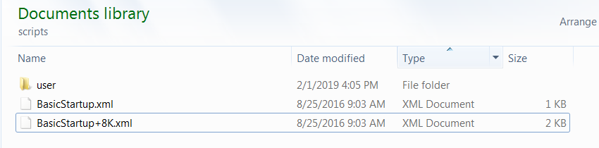
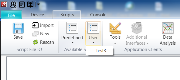
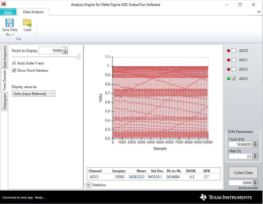
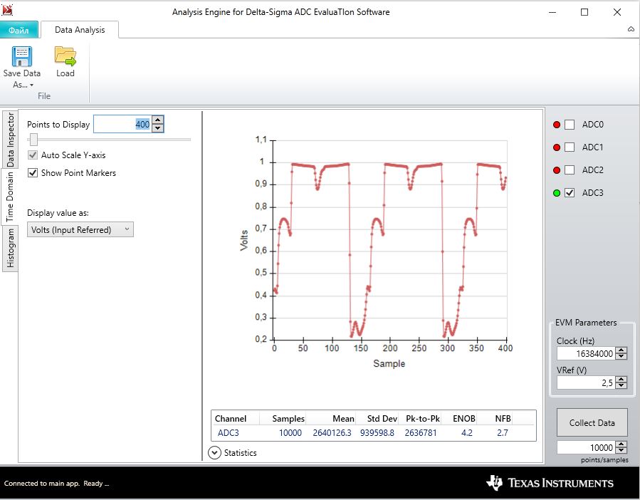
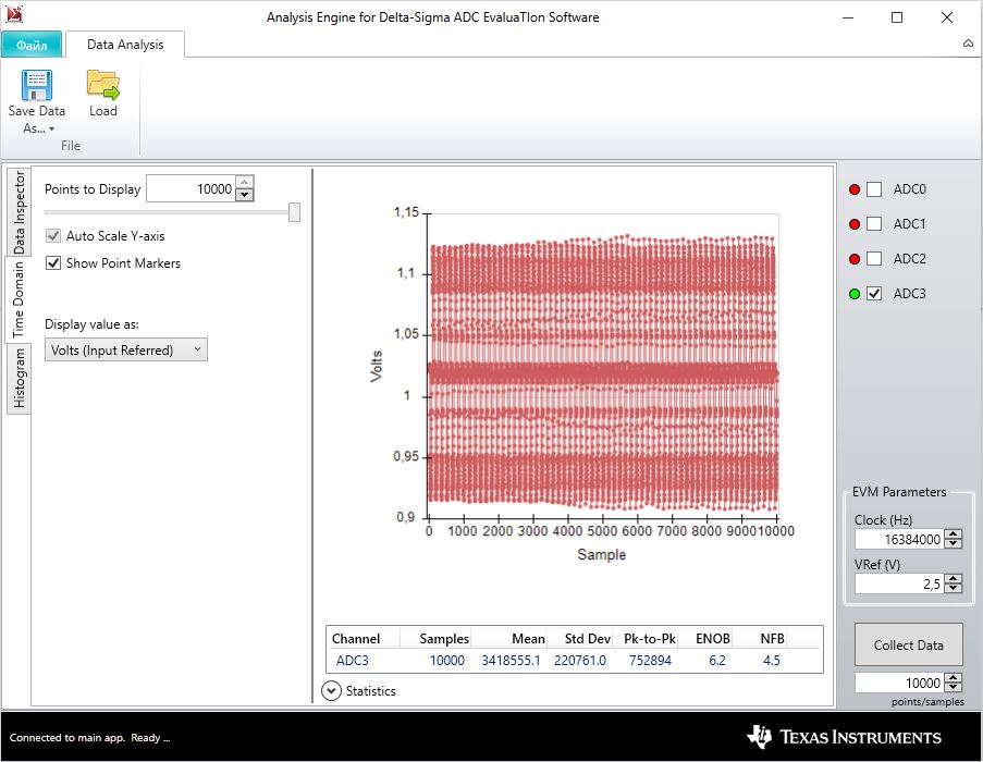
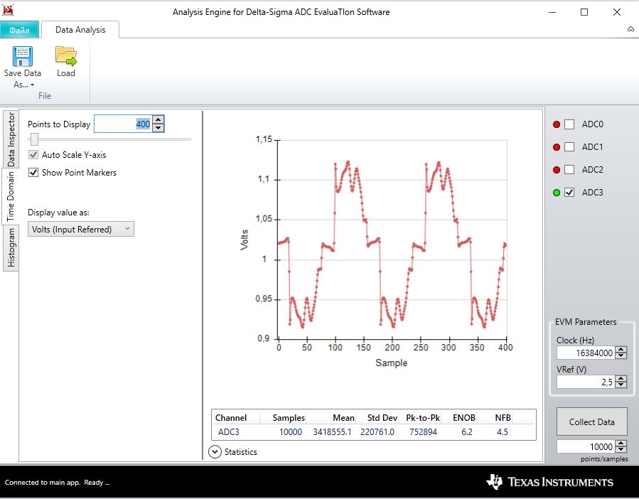
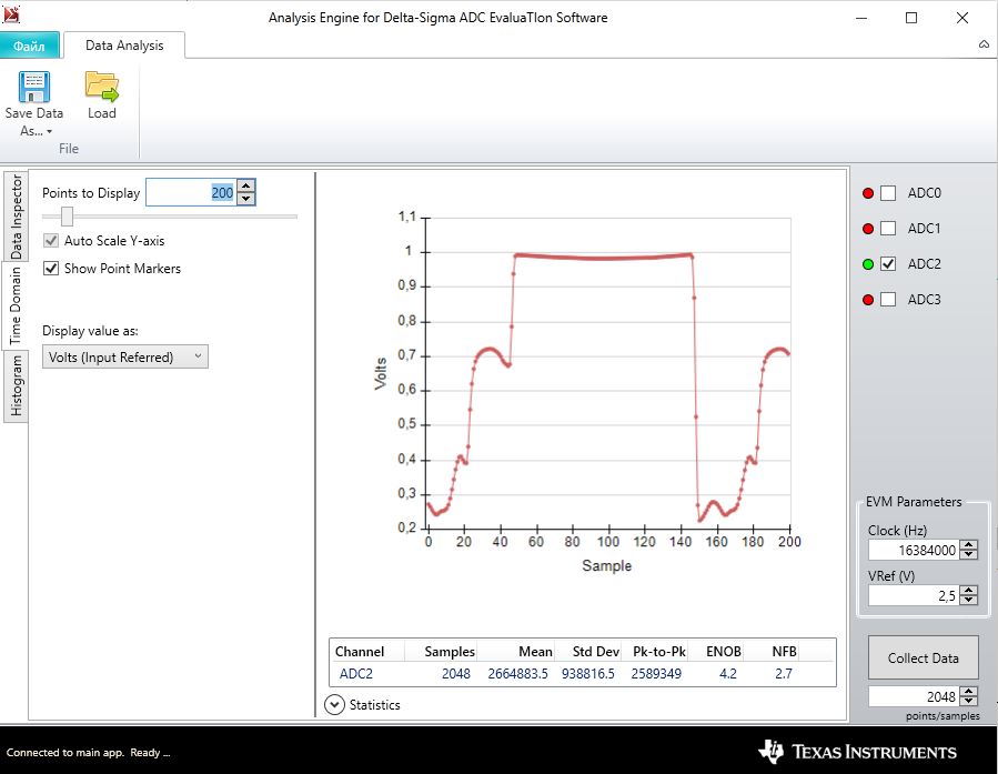
2) I am use "Delta-Sigma ADC EvaluaTIon Software". I saved the script. The next time I run the program and import the script, as a result, the program crashes.

  • Kost,


    Thanks for your post. I took a look at the EVM and checked the settings.

    1. For these lever switches (S4, S5, and S8), I believe that you are right and that the silkscreen is incorrect. Whoever did the layout may have been confused because the setting of the switch is opposite of the the connection made from the switch contact. For example if the switch is thrown up, then the connection is made from the center tap to the lower contact.

    2. I'll need some more time to check on the scripting problem. Regardless, are you able to run the device with the console commands? Does the program crash when you try to import a script?


    Joseph Wu
  • 1) Perhaps there should have been other switches)

    2) I am use Predefined Scripts: Basic startup with datarate 8KSPS. Its work. and I add WREG 0D 68 to turn on InternalREF. Then change Name "Basic startup with Datarate @ 8kSPS 1" and save as My1.xml. Restart program -> Scripts -> Import -> My1.xml == program crash.

  • Kost,

    I think I have a solution for your script loading problem. I believe that the software is looking for a "user" directory for the script. When the software doesn't find the directory, it doesn't create the directory and crashes the program.

    First, create a directory called user in the scripts folder. It should be in your documents library in Windows. The path should be something like this.

    C:\Users\*****\Documents\DSEvalSW\Devices\ADS131A04\scripts\user

    There are already some predefined scripts that come with the software, so it should look like this:

    If you have a script file (.xml), save it in the user directory. If you can't, just save the script and paste it in the directory.

    After that, open the software and click on the Scripts tab. Under the "User" button, you should be able to see the scripts saved in the directory and click on the script you want. If the "User" button is greyed out, then you may need to click "Rescan" so that the software can see the scripts directory.

    That should get you to your script. If you continue to have problems, post back and include the script file, and I'll see if I have similar problems. Also, the software has a log file that can be helpful for debug. You might want to include the files in the following directory:

    C:\Users\*****\Documents\DSEvalSW\Logs\

    Hopefully this solves your problem. Post back if you continue to have problems.

    Joseph Wu

  • Thanks! it's work.

    I have a new problem in board:

    1) R89 is 0 Om. Is it right? I think is error. I connect via j10 through a buffer and as a result I get nothing. Replacing it with 10k - is ok.

    2) I use the scheme "Figure 102. Typical Power Metering Connections" and the nominal values specified in "10.2.2 Detailed Design Procedure" from the datasheet ADS131A0x. I'm measuring  constant voltage by connection to the j9. I give through the calibrator 50B of a constant signal. The result is in the figure.

    If i use buffer - it's ok. May be i misconfigured ADC?

  • Kost,


    Looking at the buffer using R89, it looks like this should just be removed. It's possible that it was intended for some gain in the buffer with R87, but in the end, this should just be a unity gain buffer. If you've replaced this with a 10kΩ resistor, it should be ok. This only adds a small load to the buffer.

    As for the noise, I'm not sure what this problem is. What data rate are you using? Is this waveform 50Hz or 60Hz as the power line cycle in your region? Line cycle could couple into the signal with the input or the reference, but if the buffer helps, it's more likely a problem with the input.

    If this is a problem with the input voltage, I would check the output of the source to make sure that the signal stays within AVDD and AVSS, also, I'd check the grounding between the signal source and the EVM.


    Joseph Wu
  • Hi Joseph,

    For the noise i have next results: 

    Settings Board: bipolar supplies (JP11 2-3), internal reference enable (JP9 OFF and software enable), Script: Basic startup with Datarate @ 8kSPS

    1) Calibrator connected j10 1-2, buffer on. Input voltage 1V.

    it's ok.

    2) Calibrator connected j10 1-3, buffer OFF. Input voltage 1V.


    and increse


    3) Calibrator connected j10 1-3 by resistance divider, buffer OFF. Input voltage 180V, resistance divider 1MOm + 5.5kOm. Then in j10 just about 0.99V


    and increase


    4) Calibrator connected j10 1-2 by resistance divider, buffer on. Input voltage 180V, resistance divider 1MOm + 5.5kOm. Then in j10 just about 0.99V


    and increase


    5) Calibrator connected j9 1-2 by resistance divider. Input voltage 180V, resistance divider 1MOm + 5.5kOm. Then in j9 just about 0.99V. Calibrator groundin connect to EVM GND


    As you can see, the noise is periodic = 50Hz (our network). Calibrator n4-16.  ADS131 allows to measure a constant signal?

  • Kost,


    I'm not sure what is going on. I did have a chance to use the ADS131E04EVM earlier today, and I didn't see any problems with line cycle noise.

    For your test, I would start with focusing on what noise is coming in with the 1V signal without the buffer. For you, that would be the second case, without the high voltage resistor divider. What are you using for a voltage source? I would verify that you don't see the noise coming from your test voltage source.

    On a side note, it does concern me that your measurement from a voltage divider coming from a large resistor. Because the input is capacitively sampled, I generally don't like large series resistances from the measured voltage to the input of the ADC. This can cause some gain error.


    Joseph Wu
  • Joseph,

    I attempted the second case: if i plug in the oscilloscope getting good!)

    In my board broken usb connector, and the wire is soldered straight but not sealed braid. Where to solder the braid?

  • Kost,


    I'm actually not completely sure where the USB cable shielding is supposed to be connected.

    I thought that the shield should be connected to the GND, but through a resistance and filtering. However, it's not something that I know with any certainty.

    I will say that if the scope connection causes the signal to clean up, it could be that you have some sort of grounding issue. With the scope connection to earth ground, you may have removed a ground loop voltage that caused the noise that you see.


    Joseph Wu
  • Joseph,

    Everything became good. In the datasheet on the "Figure 102. Typical Power Metering Connections" did not pay attention to neutral and gnd. Shorted out 1-2 in j10 and everything became ok. Thanks for answers!

  • Kost,

    I’m glad that worked for you. If you have any other problems with the EVM, feel free to post back.

    Joseph Wu

  • Kost,


    After making a few more checks, I wanted to follow-up to this particular post. On the EVM that I have, the silkscreen for switch S4 is correct, the switch should be set to the up position for use with the software.

    With S4 up, plugging in the USB cable, LEDs for D1, D2, and D4 come up green and the software recognizes the EVM. With S4 down and re-plugging in the USB cable; the EVM is in manual mode and while D4 comes up green, D3 becomes red and the software does not recognize the device.

    It is possible that you have a different revision of the board. I'm not sure if there was a proto version released. Regardless, I believe that your other previous comments are correct. I believe that S5 and S8 silkscreens are reversed for Header and Buffer, R89 should be removed. Additionally, I believe that MOSI and MISO silkscreens are reversed on the J3 header.


    Joseph Wu