This thread has been locked.

If you have a related question, please click the "Ask a related question" button in the top right corner. The newly created question will be automatically linked to this question.

ADS131E08EVM-PDK: Not able to see correct ADC input on ADS131e08 EVM software scope

Part Number: ADS131E08EVM-PDK
Other Parts Discussed in Thread: ADS131E08, , THS4531, ADS131A04EVM

Hi,

I have ADS131E08 EVM PDK kit.

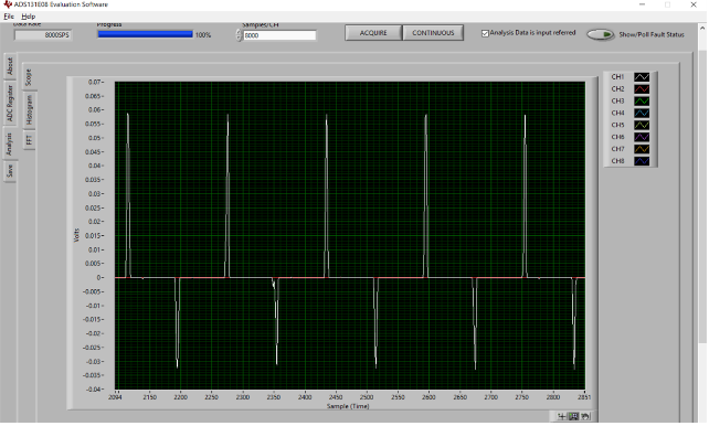
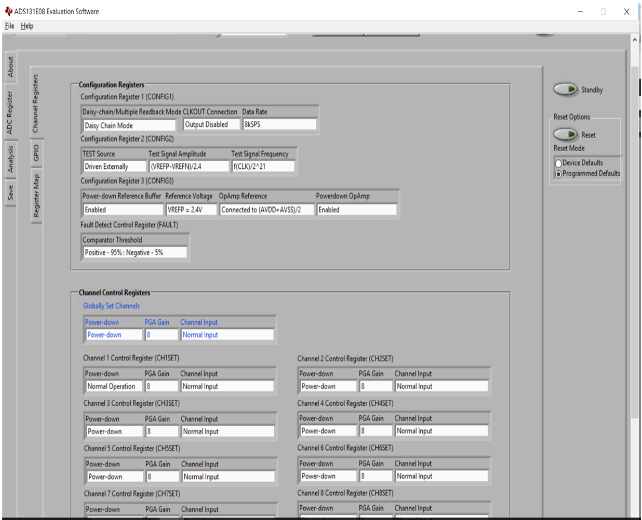
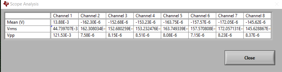
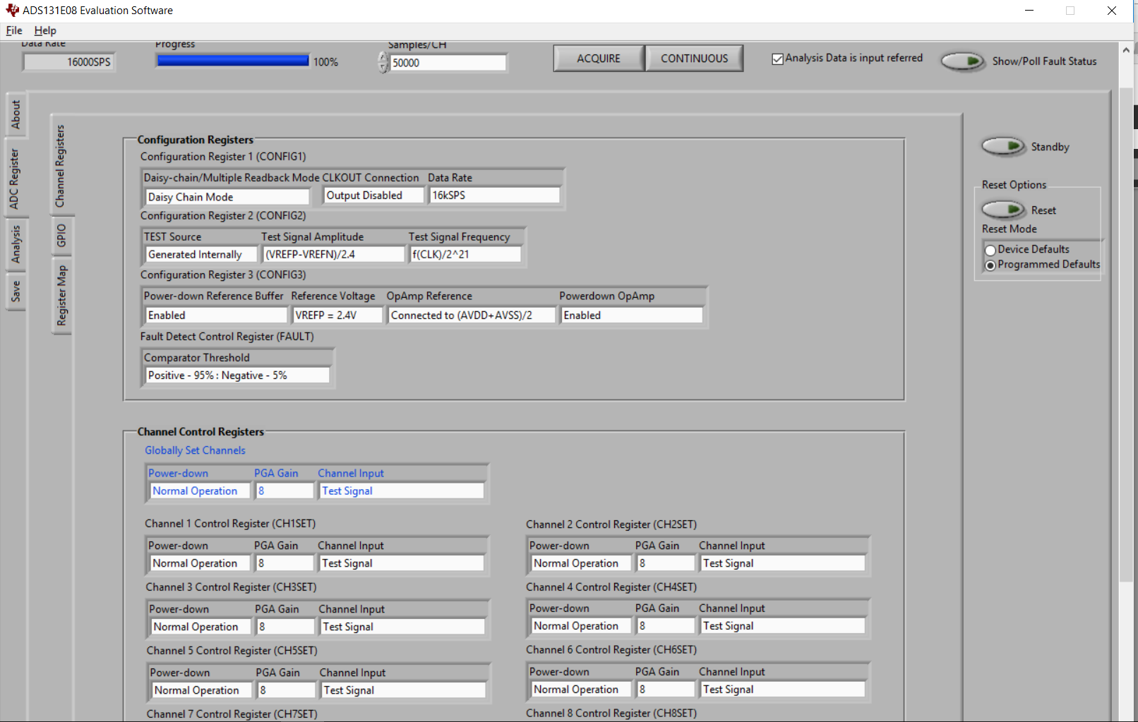
When I gave 50 mVpp input through Function generator to Channel 1 on the kit. It is giving distorted output on scope. For reference please see the screenshot of scope as well as ADC register settings:
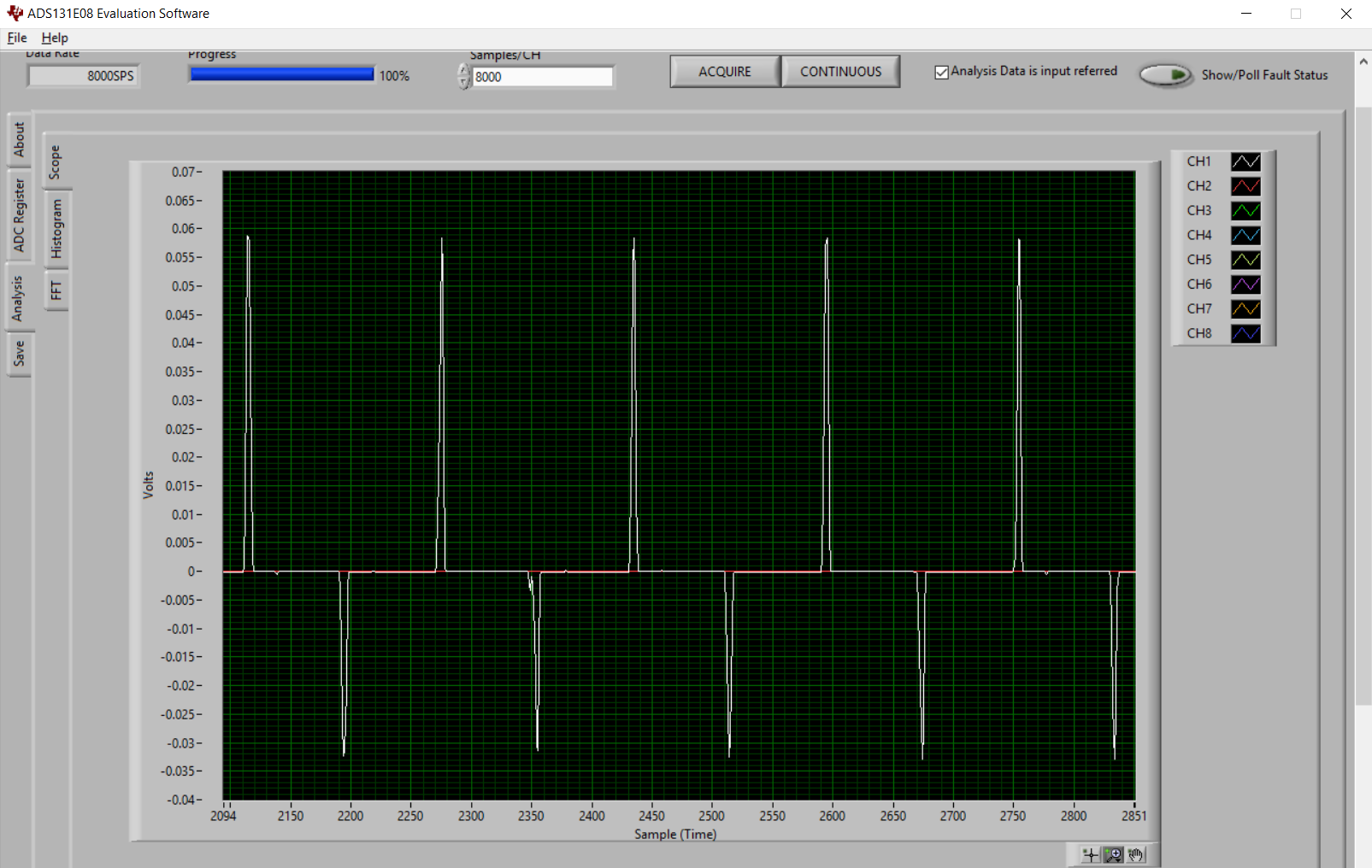
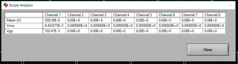
Scope analysis:

Settings:

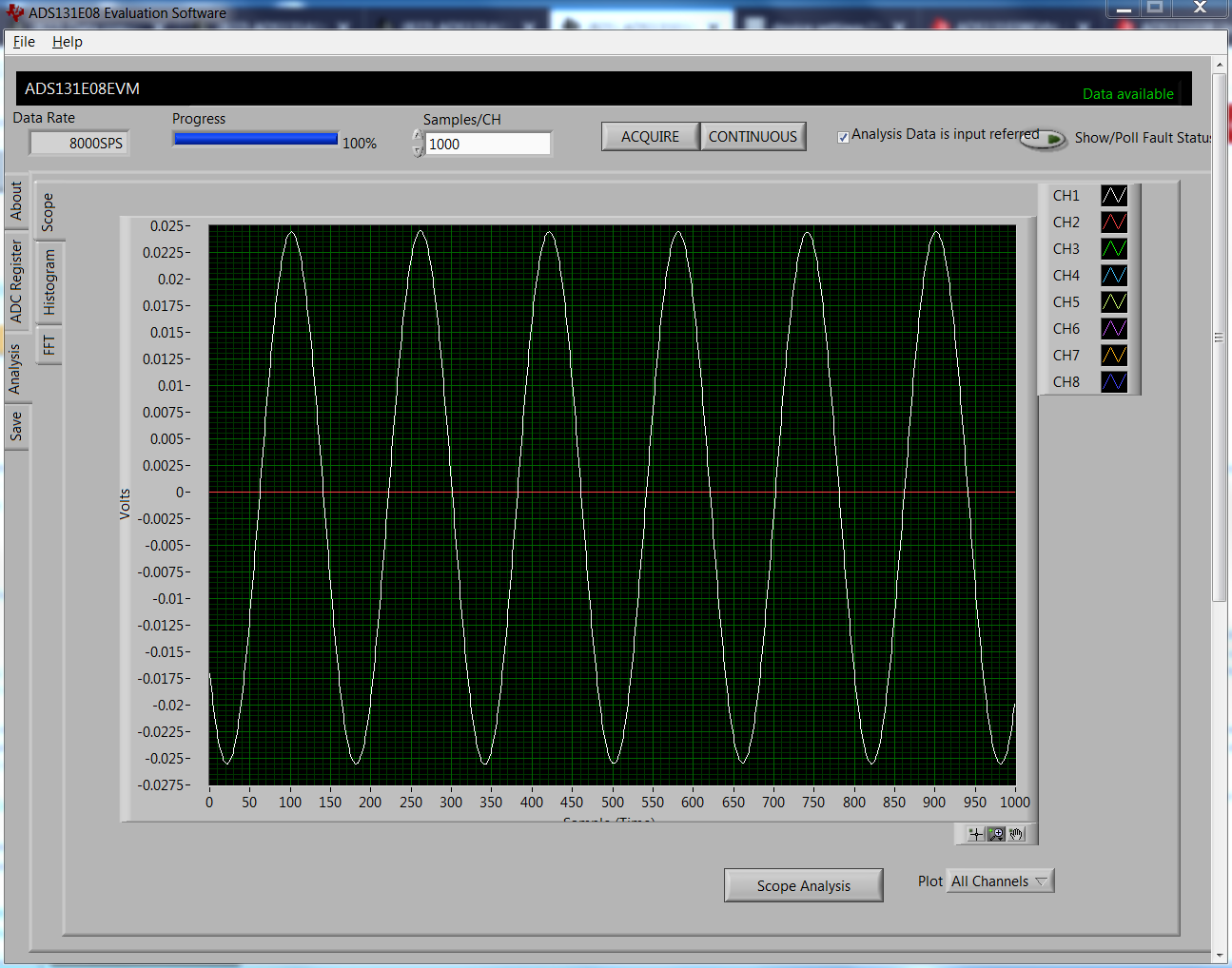
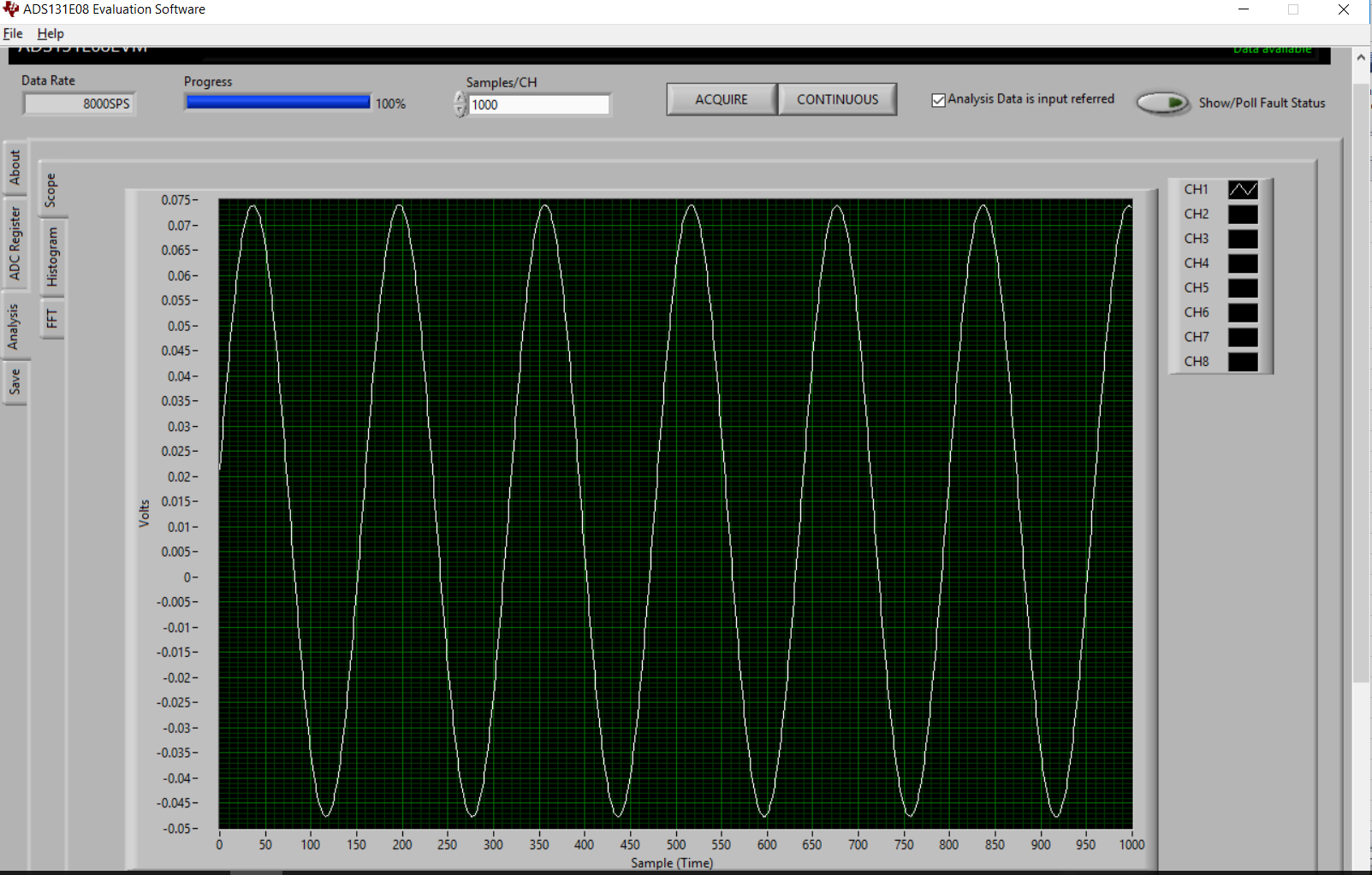
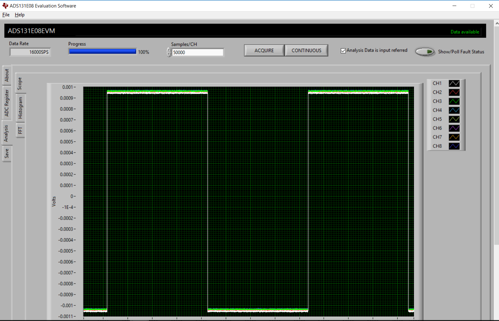
We also tried to give test input signal and we got this on Scope:

Settings:

We have given 6VDC input through power adapter to MMB0 board as mentioned in user manual.

Can you please tell us what can be the issue?

regards,

Tejaswini

  • Tejaswini,


    I don't see anything in the setup that looks unusual, so I'm not sure what is wrong yet. The test signal also looks similar to Figure 16 of the ADS131E08EVM user's guide. Have you looked at the output of the source with an oscilloscope to verify the input signal?

    One last important point is, what is the input you are using for the ADC? The PGA input range is defined by equation 4 in the ADS131E08 datasheet. Generally, the input signal common-mode voltage should be near mid supply, especially if there is a moderate amount of gain for the input signal.

    Review the equation in the datasheet and let me know how you have the input signal set up. This might get you going on the evaluation.


    Joseph Wu
  • Hi Joseph,

    Yes we checked the analog input on oscilloscope also.

    In our case our AVDD is 2.5V and AVSS is -2.5V so ideally Common mode voltage should be zero , am I correct or wrong?

    And we are giving 50 mVpp input the through Function generator to Channel 1 on the kit and we are getting following waveforms:

    Can you please tell us Exactly which type of waveform we should get Square wave or Sign wave?

    regards,

    Tejaswini

  • Tejaswini,


    I'm sorry that I didn't answer you earlier today. I just didn't have a chance to put together the ADS131E08EVM to look at the setup.

    If you do have the EVM power supplies set to ±2.5V, then the setting the function generator to have a common-mode input of 0V would be ok. I was concerned that you had left the supply as unipolar.

    As I mentioned in my last post, I think it's worth looking at the input voltage with an oscilloscope, just to check to see that the signal isn't doing something unexpected.

    I'll try to put together the EVM to test it with a similar signal source. In the meantime, can you describe the device settings and the signal source you're using?


    Joseph Wu
  • Hi Joseph,

    Yes, we did check the input voltage with an oscilloscope and it is showing correct Sign wave with 50 mV Peak to Peak Voltage amplitude and 50 Hz freq.

    (We are giving using Function generator as a signal source - Tektronix AFG3101C (100 MHz, Single Channel, 1 GS/s, Arbitrary/Function Generator)

    Following are the device settings we configured using ADS131E08EVM-PDK software:

    Tejaswini

  • Tejaswini,

    I was able to connect up a function generator and measure a 50Hz, 50mV input signal with the ADS131E08EVM:

    I did have some initial problems setting it up, which may be similar to what you're seeing. There were some periodic spikes, and the output was similar to yours, but they cleared up when I made sure the function generator and the EVM had the same common ground.

    The negative output of the function generator is likely not a ground and the ADC input requires some set common-mode voltage. In the end, I needed to make an extra connection from the function generator negative output to the EVM ground. In my case, this was TP11. After that, the ADC data came out clearly as a sine wave.

    Joseph Wu

  • Joseph,

    Thanks for your help,

    As you said, I connected one extra connection from function generator negative output to EVM ground (TP11 only). I got the sign wave on scope!

    Fo 50 mVpp input -  You are getting exact 50 mVpp (+- 25 mV) output on scope(from your previous screenshot) . While I am getting twice of that i.e. 100 mVpp and also there is some offset in my waveform (in your waveform offset is zero). What can be the reason for that offset? 

     Please check the waveform & Scope Analysis.

    Regards,

    Tejaswini

  • Tejaswini,


    If the output is 2x the value you expect in this set up, there are two things that you need to check.

    First, check that the reference value listed in the software is correct. If the value of the reference is 1/2 of the expected value, then the software will report a value 2x larger than expected.

    Second, often function generators have will report an amplitude of the output voltage when the output voltage has a 50Ω termination. The output impedance of the function generator is 50Ω and you get the reported value when there is a 50Ω load. If the function generator drives a high impedance, the output will be 2x the reported value. I was using an Agilent 33120a and that's the way the function generator reports the value.

    The best way to verify that is to get an oscilloscope and check the value for yourself. An amplitude of ±50mV might be a bit small, but it should be something you can measure.


    Joseph Wu

  • Joseph,

    In our case our signal is Differential so if we connect Negative terminal of Function Generator to the TP11 (AGND) it will act as a Single ended (as mentioned here- https://www.mccdaq.com/TechTips/TechTip-4.aspx ).

    Can you please tell us for Differential signal (IN+ and IN-), What to connect to AGND ?

  • Tejaswini,

    For a fully differential signal, it's likely you'll need something a little different for your setup.

    If you have a function generator, often this is set up as some sort of pseudo differential output. One input is held to ground while the other goes up and down around that. In this case, it's similar to this:

    To get something that is fully differential, you would probably need some sort of buffer from a fully differential amplifier. If you look at the EVM for a different board, the ADS131A04EVM uses a THS4531 for a buffer. This buffer has a output common mode set point. On this particular board, this Vocm connected to a cap to ground, which sets the output to mid supply, but it could also be connected to ground. It would look like this:

    I think you'd need a fully differential amplifier to get a true differential signal.

    Joseph Wu

  • Thank you so much Joseph for your support.

    We will add fully differential amplifier as you said.

    Regards,

    Tejaswini