This thread has been locked.

If you have a related question, please click the "Ask a related question" button in the top right corner. The newly created question will be automatically linked to this question.

ADS8661: How to communicate with ADS8661

Part Number: ADS8661

Hello,

I am trying to work with the device but with no success, the datasheet is not clear enough.

1) I am using SPI MODE0.

2) I am sending data in 8bit data groups (same when receiving data) ie sending 8 clocks at a time, hence for receiving a 32bit register I am sending 4 groups of 8 clocks and not a continuse stream of 32 clocks.


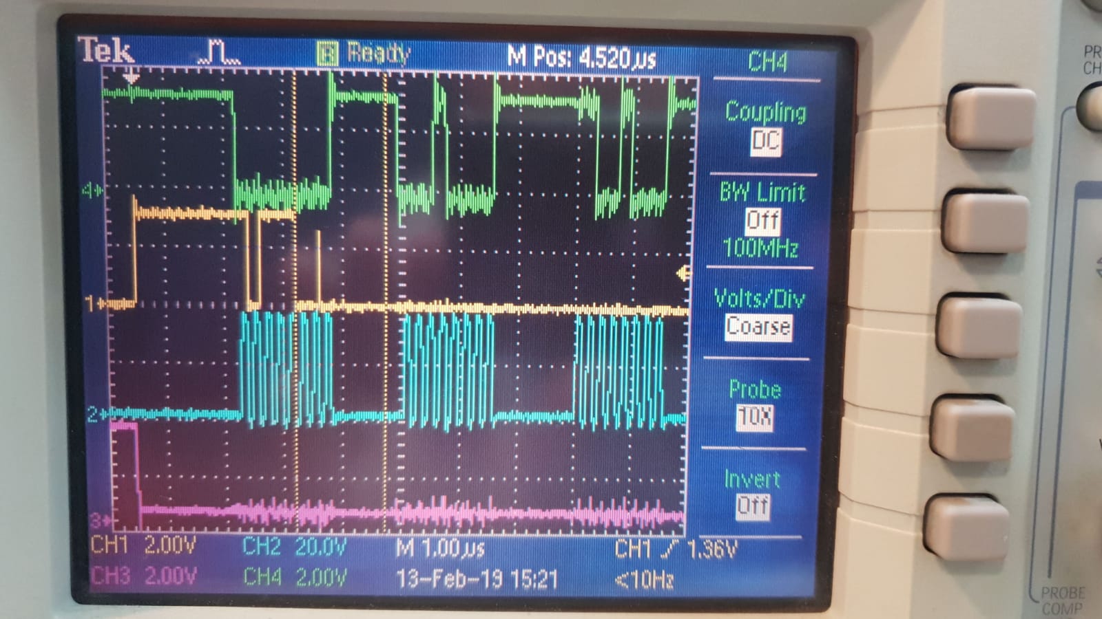
I would like to have a clear timing diagram of reading sampled signal data and reading/writing to the registers (ie how to read the device ID register).

Thanks.

  • Hi Haim,

    On power-up or after coming out of any asynchronous reset, the device supports the SPI-00-S protocol for data read and data write operations, so make sure your configuration for phase and polarity on your microcontroller is 00.

    To read or write registers, please refer to the command list in table 5, and the description in section 7.5.1/ 7.5.2.

    The command to read device ID:  

    1. Command           Address                  Data
    2. <11001_00> <0_00000010><00000000_00000000> which is 0xC8020000.
    3. See timing in Figure 71. The device ID will be shown in bit 0-3 in next frame with /CS and SCLK.

    Note that the default device ID is 0000b after power up. Also, if any of these commands are provided in a particular data frame F, that command gets executed at the rising edge of the CONVST/CS signal.


    For data conversion and reading, please refer to Figure 3 which is a timing diagram for standard SPI interface(CPHA=0).

    1. Issue a CONVST/CS rising edge from low to high level to start a conversion.
    2. When RVS goes high if RVS pin is monitored by microcontroller or after wait for tconv_max (550ns for ADS8661), the CONVST/CS falling edge from high to low level can be issued which will initiate a data transfer.
    3. Send SCLK to ADC and read the data on SDO from ADC. Check timing in Figure 1 and 3.

    Regards

    Dale