This thread has been locked.

If you have a related question, please click the "Ask a related question" button in the top right corner. The newly created question will be automatically linked to this question.

ADS1293: 3 lead ECG application with ADS1293

Part Number: ADS1293
Other Parts Discussed in Thread: ADS1298ECGFE-PDK

hi team

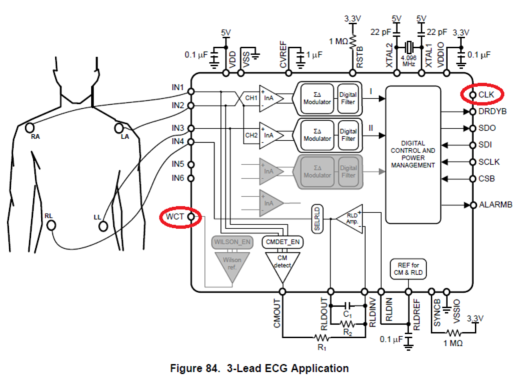
my customer is generating a schematic for 3 lead ECG with the ADS1293

we'd like to check the following questions

1. can all the power source to the ADS1293 input at 3V ? (eg. VDD, RSTB, XTAL2, VDDIO) or must be at 3.3 and 5V? if 5V is needed is there a suggested boost IC that's commanded? (this will be 1S lithium battery application)

2. do we need RC filters before the input to IN1~IN4?? if yes, what's the suggested implementation?

3. in the figure 84, is the pin WCT and CLK not connected? is it ok to left it floating?

  • Hi John,

    Thanks for your post!
    Please see table 7.3 Recommended Operating Conditions in the datasheet. If required for your customers specific application, I do not have a boost IC in mind. 

    RC filters are highly recommended and should be tailored to the customers system. The implementation from the ADS1298ECGFE-PDK user's guide is a good place to start, and this video can assist with further customization: https://training.ti.com/ti-precision-labs-adcs-math-behind-r-c-component-selection?cu=1128375:1230:0

    WCT is an analog output and CLK is either an internal clock output or external clock input, both of these pins are primarily intended for 8 or 12 lead ECG applications as shown in figure 88. If unused, they will be disconnected internally and can float externally.