This thread has been locked.

If you have a related question, please click the "Ask a related question" button in the top right corner. The newly created question will be automatically linked to this question.

ADS124S06: Differential measurement and ADC counts output

Part Number: ADS124S06

Hello,

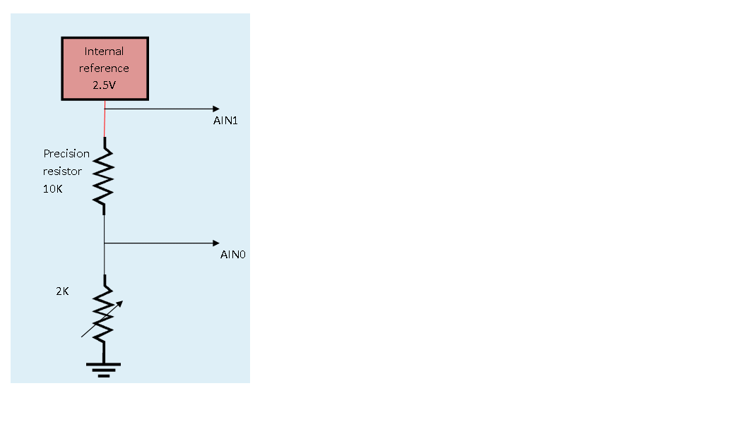
we are using ADS124S06 in differential configuration, using ADC internal 2.5V reference. The input to ADC comes from the voltage divider as follows:

AIN1=2.5V internal reference

AIN0=signal=0.4166V (signal from divider with 10K and 2K precision resistor)

We are however not getting the correct value in differential mode measurement. The configuration that we have kept for register settings are:

( STATUS_ADDR_MASK, 0x80 );

                ( INPMUX_ADDR_MASK, 0x10 );                               

                ( PGA_ADDR_MASK, 0x00 );

                ( DATARATE_ADDR_MASK, 0x81 );

                ( REF_ADDR_MASK, 0x3A );

                ( IDACMAG_ADDR_MASK, 0x00 );

                ( IDACMUX_ADDR_MASK, 0xFF );

                ( VBIAS_ADDR_MASK, 0x00 );

                ( SYS_ADDR_MASK, 0x10 );

                ( OFCAL0_ADDR_MASK, 0x00 );

                ( OFCAL1_ADDR_MASK, 0x00 );

                ( OFCAL2_ADDR_MASK, 0x00 );

                ( FSCAL0_ADDR_MASK, 0x00 );

                ( FSCAL1_ADDR_MASK, 0x00 );

                ( FSCAL2_ADDR_MASK, 0x40 );

                ( GPIODAT_ADDR_MASK, 0x00 );

                ( GPIOCON_ADDR_MASK, 0x00 );                           

Please update whether these settings are correct or not for doing differential measurement.

As per above figure, we should get 0.41 V in measurement while the ADC counts (6990303) that we are getting is close to 1.04 V, 

The required figure of 0.41 V can be get if we subtract the twice of 1.04 V (1.04 V * 2 = 2.08 V) counts from 2.5 V. Please suggest the correct method for computing final vale in differential measurement.

Please support for possible mistake in register settings, do let us know for any clarifications needed for the specified problem.

Regards

Prateek

  • Hi Prateek,

    The configuration settings are ok. The differential measurement you are making is across the the 10k resistor and not the 2k pot. So the voltage to be expected would be much larger the 0.41V. The voltage across the divider would be 2.50V*(10k/12k) which would be 2.083V. The code being returned (6990303) would be multiplied times the voltage value of 1 code (LSB) which is determined by +/-2.5V(2^24). This results in a calculated value of 2.083V. So you are getting back what you should expect, but you are using the wrong calculations.

    Best regards,
    Bob B
  • Hi Prateek,

    I always suggest to calculate the thermistor value in this kind of configuration the following way.

    The relationship between the output code of the ADS124S06 and the applied differential input signal (VIN) is:
    Code / 2^24 = VIN / (2 x VREF)

    In your case VIN = AIN1 - AIN0,
    where VIN = VREF x RBIAS / (RBIAS + NTC)

    This results in:
    Code / 2^23 = RBIAS / (RBIAS + NTC)

    Comparing this with the code you are measuring, the ADS124S06 seems to yield the correct result.

    Regards,

  • Hi Joachim,
    Many thanks for your reply. The above formula leads us to correct results.
    However I do have a query that why is this factor of 2 added in this equation?
    Also does this equation remains same whether we are using the ADC in single ended/ differential mode?
    Also, when the ADC is used in differential ended mode, do we have to enable the PGA, also is there any any difference between PGA disabled and unity PGA?

    Regards
    Prateek
  • For the above differential signal input configuration to ADS124S06 in layout shared in post, we are interested in finding out the value of 2k pot by measuring the ADC_Raw_Counts of (AIN1 – AIN0).

    For differential input between AIN1 & AIN0, we obtain ADC_Raw_Counts 6990840

    If, we do single ended measurement i.e AIN0 w.r.t. GND, then we obtain ADC_Raw_Counts 1398023

    If we use the formula  R(precision) * ADC_Raw_Counts / (2^23 – ADC_Raw_Counts) , provided by TI for obtaining resistance value in single ended configuration, then we obtain correct resistance value i.e. 2 kOhms.

    If we use the same above formula for differential measurement it gives resistance value of 50.0143 kOhms which is incorrect.

    For calculating resistance from the differential input configuration, we are using below formula:

    R(pot) = R(precision) * ADC_Raw_Counts / (2^23 – ADC_Raw_Counts)

    Please suggest whether the above formula is justified for this calculation??

    Regards

    Prateek

  • Hi Prateek,

    What I was attempting to show in my first response is that you are not calculating correctly. There are many ways to make this calculation depending on whether you are looking at a voltage or a resistance, but they all relate to Ohm's Law in some way. Your initial question was in regards to voltage. If you subtract the voltage returned from the ADC from the value of the reference, you get the voltage across the pot. You can turn this into a ratio of codes relative to voltage.

    When determining the resistance you can use the formula Joachim showed which is the ratio of the codes returned to the ratio of the resistances. When manipulating the ratio formula to solve for the pot, you must make sure that the terms and rearranging of the terms are all correct. By taking the formula Joachim has given and solving for R(pot):
    R(pot) = R(precision) *((2^23/ ADC_Raw_Counts) -1)
    So R(pot) = 10k((2^23/6990840) - 1) = 2k

    Regarding the PGA, at a gain of 1 you can have the PGA enabled or PGA disabled. PGA enabled allows for higher input impedance, but reduces the input range and you must be above 0.15 V above AVSS. For PGA disabled, you can measure all the way down to AVSS - 0.05V.

    Best regards,
    Bob B
  • Thanks Bob.

    Hi Prateek,
    just to clarify further. If you measure from AIN0 to GND, then you will have to bypass the PGA in order to meet the input voltage range requirements of the ADC.

    Regards,
  • We have one more query regarding data format of ADS124S06. Is there any method to configure the ADC’s analog input from 0 to Vref so that the step size could be reduced to half for more precise measurements?

  • Hi Surya,

    unfortunately this is not possible with ADS124S06.
    The LSB size is fixed to (2 x VREF) / (2^24 x Gain) independent of using single-ended or differential measurements.
    Reducing the LSB size would actually not help to improve the performance because the noise of the ADC is larger than the LSB size.

    Regards,