see the waveform please,
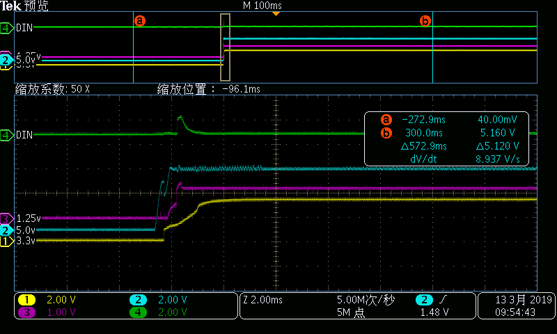
blue signal is pin DIN, the data set is in the start phase, so we can't see the change of data(0 to 1, 1 to 0 and so on) ;yellow signal is controlled object;pink signal is OUTC output voltage;green signal is OUTD output voltage.
the set value of OUTC and OUTD are same, so the OUTD should be same with OUTC, but I find after data received, OUTD output a voltage value which is higher than set value immediately, and it can output set value at the end of the data conversion process.
the work is properly after replace a new chip.
I want to know what is the cause of failure of this chip? And what should I pay attention to in the future to avoid failure again?